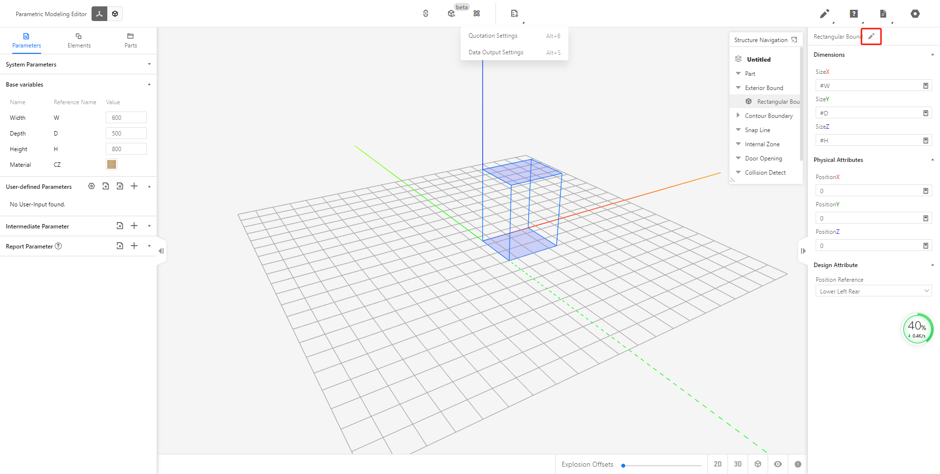
1. Model property bar
The model property bar belongs to the property bar of the entire model and is located on the far right side of the editor page. Divided into
1 model name
2 product name,
3 picture settings
4 component attributes
5 front-end usage attributes
1.1 Model name
The model name is the name given when the model is saved, and can only be modified in the edit details of the product details in the merchant background (the model name of a new model that has not been saved is displayed as unnamed).
1.2 Product name
The product name will appear in the model attribute column only when the saved model is opened, and the newly created model will not appear. Clicking on the product name will automatically jump to the product details page of the merchant backend, which is used to view the product details and save the path of the model.
1.3 Picture settings
Used to set the preview image and the annotation image. After the preview is set, the model rendering is completed and the set preview will be displayed in the merchant's backstage and tools; the annotation map will display the set annotation map after selecting the model in the tool and hovering the mouse on the parameter area.
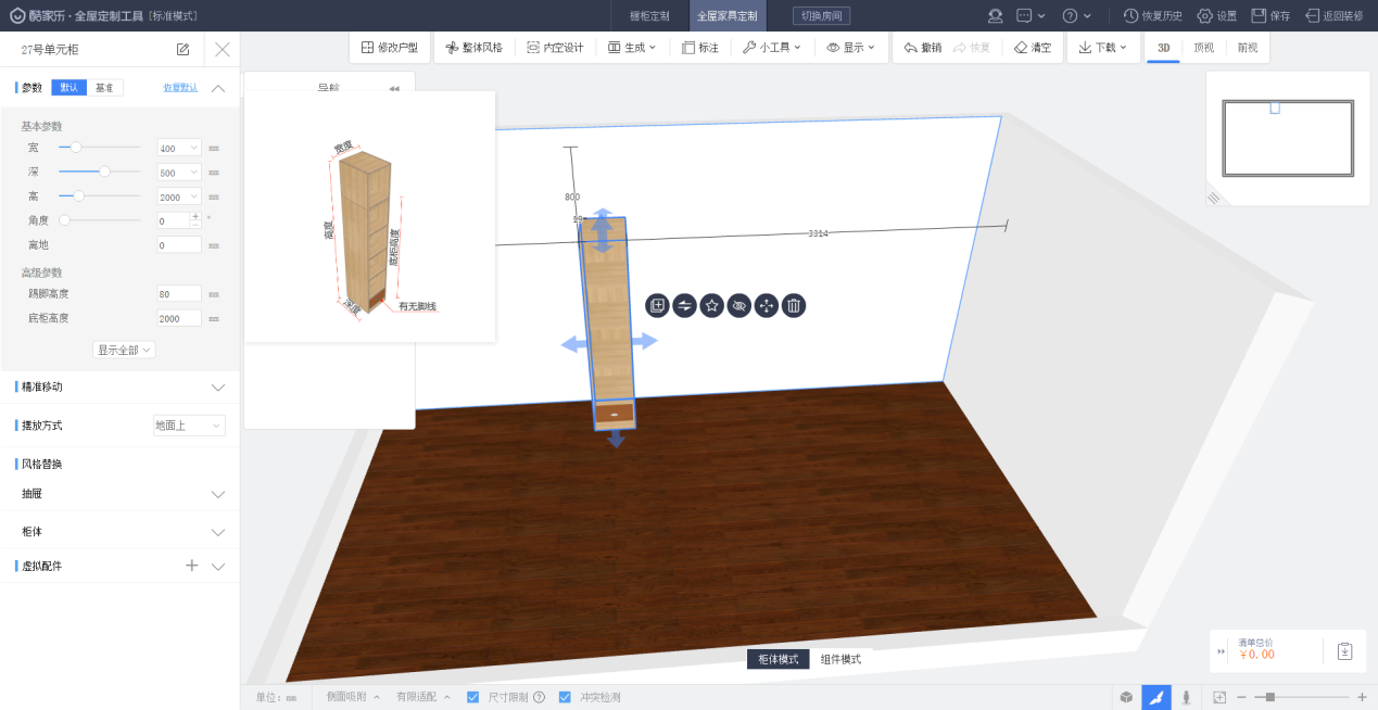
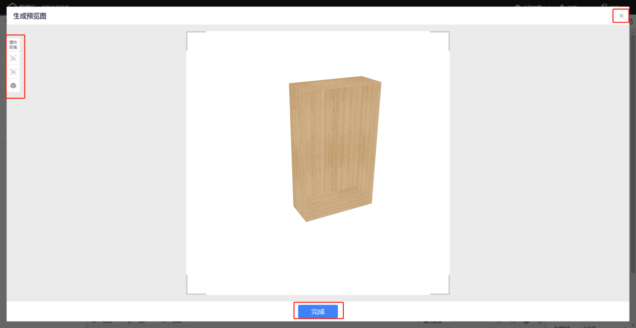
Create Preview image: Click Create in the preview image box to enter the page for generating preview images. You can set the explosion distance and view mode on the left side. In the middlebox, press and hold the left button to adjust the direction of the model. Right-click and hold the move to adjust the position of the model. After the setting is complete, click Finish below.
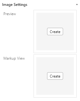
Create annotated map: Click Create in the annotated map box to enter the page for generating annotated map. You can set the explosion distance and view mode on the left. In the middlebox, press and hold the left button to adjust the direction of the model, right-click and hold the move to adjust the position of the model. After setting, click the next step below. Set the label type, text, color, etc. on the left, and click Finish below after setting.
1.4 Part properties
The component properties are the library, model category, and component calling method. The library category is used to display the name of the selected library category; the model category is used to display the specific subcategory name under the library category selected when creating; the component call mode is used to control the call mode when the entire model calls the sub-model (Origin, Left Back Down) The default is to call left back down.
1.5 Front-end usage attributes
Front-end usage attributes are used to control some functions of the model in front-end tools.
Generate tabletop, generate top line, generate foot line, and generate light line: used to control whether the model can automatically generate tabletop, top line, foot line, and light line in the tool. Only control the automatic generation without affecting the selection and generation. Select "Yes" for the model to automatically generate lines in the tool, and select "No" for the model to not automatically generate lines in the tool. The default is not selected. The tool will determine whether lines can be automatically generated and which ones are automatically generated according to the model category. line;
Component can be deleted: It is used to control whether all sub-models in the tool (such as panels in the cabinet) can be deleted, "Yes" can be deleted, "No" can not be deleted, the default is not selected can be deleted.
Replaceable parts: used to control whether the styles of all sub-models (such as door panels and drawers in the cabinet) that can be replaced in the tool can be replaced, "Yes" can be replaced, "No" cannot be replaced, default Not selected can be replaced.
Insert virtual model: It is used to control whether virtual hardware can be inserted in the tool. "Yes" can be inserted, and "No" cannot be inserted. By default, it can be inserted if it is not selected.
Overall recognition: It is used to judge whether the pattern is recognized as a whole in the tool. The overall recognition can only recognize the model in the tool and not recognize the sub-model as a whole. The sub-model cannot be selected and modified in the tool. It is mainly used to call too many sub-models. When dragged out of the tool, it is stuck or does not display, etc., which improves the smoothness of complex models in the tool's 3D scene. "Yes" for overall recognition, "No" for overall recognition, default is not selected is not for overall recognition.
Component parameters can be edited: used to control whether all sub-models in the tool (such as panels in the cabinet) can edit the parameters separately, "Yes" can be edited separately, and "No" cannot be edited separately. By default, yes is not selected Can be edited individually.
Unification of texture: It is used to control whether the model has the function of the unification of texture. By default, whether the unification of texture is enabled or not. It is generally used when the texture of the entire door panel is required to be consistent for lofted door panels.
Transfer hidden variables: When the sub-model in the model is replaced in the tool, whether the hidden variable in the replaced sub-model is passed in the JSON file is mainly used for merchants that need to connect to production.
System variable logic: used to control the system variable in the tool by which logic is used to determine the control. The "tool logic" system variable is determined by the tool with the preset inherent logic, and the "editor logic" system variable is in the tool When using, the value is determined by the rules set in the editor. For example, the mask value on the door panel is written with a formula to determine the specific mask value in different situations. This needs to be determined by the rules set in the editor. In this case, you need to select "Editor Logic". The default "not selected" is the selected tool logic
Automatically generate sliding doors: used to control whether the model can automatically generate sliding doors in the tool, and only control automatic generation without affecting selection generation. Select the "Yes" model to automatically generate a sliding door in the tool, and select the "No" model to automatically generate a sliding door in the tool. The default is not to select "No".
2. Sub-model property bar
Click the selected sub-model to call, and the sub-model attribute column will appear on the far right of the page, which is divided into 1 sub-model name, 2 sub-model product name, 3 size attribute, 4 physical attributes, 5 system attribute, 6 component attribute, 7 style attribute, 8 front-end usage attributes.
2.1 Sub-model name
The sub-model name is the name of the called sub-model when it is saved. The name of the sub-model is also displayed in the list. You can double-click in the structure navigation or click the button to the right of the sub-model name to modify it.
2.2 Sub-model trade name
Clicking on the product name will automatically jump to the product details page of the merchant backend, which is used to view the product details and save the path of the submodel.
2.3 Size attributes
The size attribute is the size of the sub-model in the coordinate axis, and the size of the sub-model in the entire model is defined by modifying the size attribute of the sub-model for modeling.
The inherited attribute is used to replace the sub-model, whether to inherit the current attribute value, "Yes" means that the replaced sub-model inherits the size of the sub-model before the replacement, "No" means not to inherit, and the default is not selected as inherit.
2.4 Physical properties
The physical properties are the XYZ position and rotation angle of the sub-model in the coordinate axis, and the position and rotation angle of the sub-model in the entire model is defined by modifying the physical properties for modeling.
2.5 System Properties
Sub-model system attributes: Because of the different categories and system variables of the newly-created sub-models, the sub-model system attributes are different, such as the material direction and offset attributes of the plate, and the cover method, cover value, gap, and other attributes of the drawer.
The inherited attribute is used to replace the sub-model, whether to inherit the current attribute value, "Yes" means that the replaced sub-model inherits the system variable value of the previous sub-model, "No" means not to inherit, and the default is not selected as inherit.
2.6 Part properties
Component attributes mainly include the reference name, material, and advanced parameters of the sub-model
Reference Name: mainly used when calling @ syntax
Material: divided into selection and reference. Selecting "Select" requires selecting a material in the material library and the sub-model will not change with the material changes under the model's custom variables. Selecting "reference" requires writing the "#CZ" sub-model It will change with the material changes under the model custom variables.
Advanced parameters: display the self-added custom variables (advanced parameters) on this sub-model
The inherited attribute is used to replace the sub-model, whether to inherit the current attribute value, "Yes" means that the replaced sub-model inherits the component attribute value of the sub-model before the replacement, "No" means not to inherit, and the default is not to inherit.
2.7 style attributes
It is used to control the style of the sub-model. It is mainly used to add style variables to the overall model. The style variables are referenced in the style attributes to control the style changes of the sub-model with parameters.
2.8 Front-end usage attributes
Front-end usage attributes are used to control some functions of sub-models in front-end tools
Calling method: Indicates how the sub-model is called. It is divided into origin and left-back-bottom, which is consistent with the entire model modeling method. The origin represents the modeling method when building the sub-model. The modeling method when building the sub-model is that the center point is the center point. The origin call of the model is the center point. The modeling method when building the sub-model is the left-back and bottom origin call is the left-back and bottom. By default, the left, back, and bottom are called.
Hidden condition: used to hide the sub-model under a certain condition. Select "Yes" to hide the sub-model directly; select "No" to not hide the sub-model; write the condition in the condition bar below to hide the sub-model according to the condition. For example, if the writing condition is #W<300, then when the model W is slightly less than 300, this The sub-model is hidden, otherwise (W is greater than or equal to 300) is not hidden. It is not hidden by default, and the hidden sub-models will not appear in the list and will not be quoted.
Replaceable: Used to control whether this sub-model can be replaced in the tool, it can be replaced by default;
Quotation required: used to control whether this sub-model needs to be quoted in the overall model, and it can be quoted by default; change to No, this sub-model is not quoted in the current overall model, and does not affect the sub-model itself to call other models Quote at the time.
Can be deleted: Used to control whether this sub-model can be deleted in the tool, it can be deleted by default;
Style package: used to limit the styles that can be replaced in the tool for this submodel. By default, no style package can replace all replaceable styles;
The component can be deleted: It is used to control whether the sub-model called in this sub-model can be deleted in the tool, such as the panel in the drawer. Can be deleted by default;
List output: used to control whether this sub-model is output and displayed in the quotation list. If you do not select "No" in the quotation and only select "No" in the list output, then this sub-model will not be displayed in the list but the quotation will be output by default.
Editable parameters: It is used to control whether the parameters of this submodel can be individually edited in the tool, and it can be edited by default.
3. Top property bar
Door opening association: It is used to associate the door opening added and edited in the software library with the called door panel submodel, so that the door panel can be associated with the functions and attributes of the door opening.
Global variables: used to quickly jump to the background global variables to create and edit page
Output settings: Quotation settings are used to define the parameters of quotation output; data output settings are used to define the output values and output reference names of system variables and custom variables in the output files of the data interface (JSON, API, etc.)
The model structure navigation bar
Definition: used to display the sub-models and components required for model modeling
1. The role of the structure navigation bar
1. Facilitate users to quickly find what they need
2. Clear the structure and components of the entire model
2. The location of the structure navigation bar
In the upper right corner of the editor page
3. Properties of the structure navigation bar
In the structure navigation bar, there are model names, parts, model frames, contour limits, suction lines, inner voids, door openings, interference areas, and connectors.
Model name: The name of the model when it was saved. The newly created model will be displayed as unnamed.
Parts: The parameterized models (planar parts, stakeout, grid) under the component library called in the left column and the parameterized models of the component library will all be displayed and edited in the model list.
Model frame: The custom frame (rectangular frame) that comes with the system will be displayed and edited under the model frame.
Contour restriction: The contour restriction that comes with the system or the contour restriction added by yourself will be displayed and edited in this list.
Snapline: The added snap line will be displayed and edited under this list.
Internal space: The added internal space will be displayed and edited under this list.
Doorway: The added doorway will be displayed and edited under this list.
Interference area: The added interference area will be displayed and edited under this list.
Connector: The added pipe connector will be displayed and edited under this list.
4. Operation of the structure navigation bar
1. Click the button in the upper right corner of the structure navigation bar to hide or show the navigation bar; click the lower-left corner of the mouse to zoom the navigation bar.
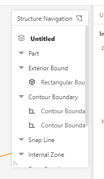
2. Hover the mouse on the component or submodel in the list and click the small eye on the left to hide and display.
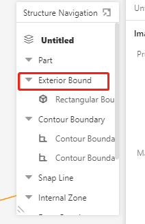
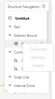
3. The components or sub-models in the list can be copied and deleted by right-clicking in the navigation bar except for custom frames. The sub-models called by the component library can be replaced (the components called by the component library cannot be replaced).
4. Click the component or sub-model in the list to view and edit the properties in the property bar on the right. The component or sub-model in the component can also be selected in the visualization interface. Other lists can only be in the navigation bar Selected. Double-click the left mouse button or click the button to the right of the name of the property bar to modify the name. The name of the submodel displayed in the quotation list is the name of the component.
