Directory of this page
I.File format requirements
II.Requirements for line outline drawings
III. Requirements for contour used in front-end tool production
Definition: Produce contour lines that meet the requirements
I. File format requirements
The file format for uploading line contours should be in the DXF format of CAD, not other formats of drawing files.

II. Requirements for line contour drawings
-
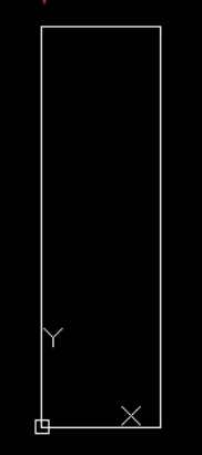
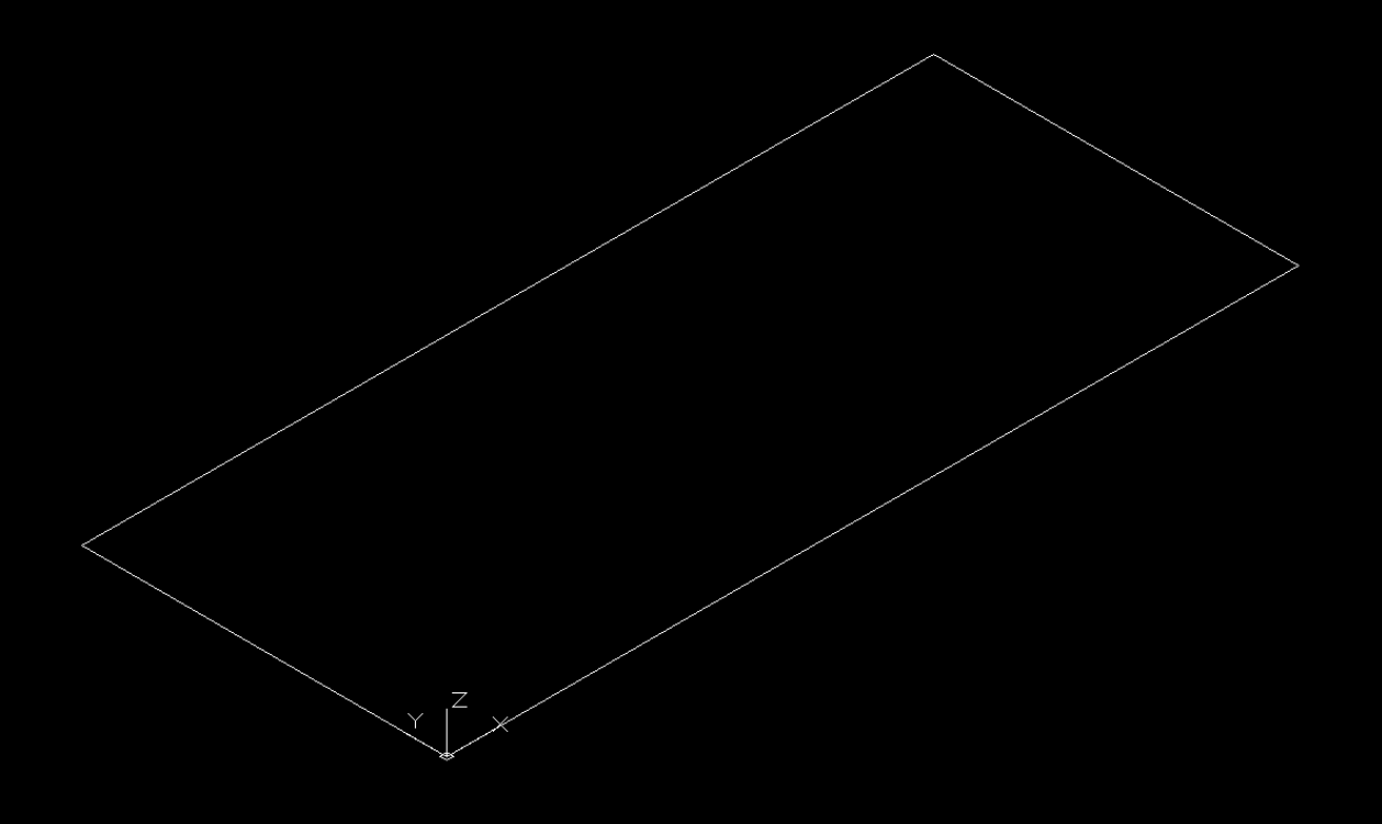
The contour in the drawing must be within the XY plane, and there should be no line segments or points in other planes;
The contour in the drawing must be within the XY plane, and there should be no line segments or points in other planes;
-
Only the outer contour needs to be extracted. Internal structural lines do not need to be reflected. Also, the contour should be able to be merged into a face, but it must be exploded for uploading. There should be no duplicate line segments in the contour, otherwise the upload will fail;
-
The contour size value should be an integer if possible. If there are decimals, take only one digit after the decimal point.
-
The reference point of the contour must be placed at the origin 0,0 (the top line contour is more special, and the reference point position needs to be adjusted according to the actual situation, refer to III-1);
Only the outer contour needs to be extracted. Internal structural lines do not need to be reflected. Also, the contour should be able to be merged into a face, but it must be exploded for uploading. There should be no duplicate line segments in the contour, otherwise the upload will fail;
The contour size value should be an integer if possible. If there are decimals, take only one digit after the decimal point.
The reference point of the contour must be placed at the origin 0,0 (the top line contour is more special, and the reference point position needs to be adjusted according to the actual situation, refer to III-1);
Operation steps: ①right click on the coordinate point, click "World", and then the coordinate point is the world origin. You cannot directly drag the coordinate point to the lower left corner of the graphic and need to move the graphic to the origin;
②Select all the graphics --Ctrl+X(cut)--Ctrl+V(paste)--enter coordinates: 0,0--press Enter to confirm.
-
The contour placement requirement is that the left side is the boundary surface of the model, the right side of the contour faces the center of the model, and the upper part of the contour is the front of the model, and the lower part is the back of the model.
The contour placement requirement is that the left side is the boundary surface of the model, the right side of the contour faces the center of the model, and the upper part of the contour is the front of the model, and the lower part is the back of the model.
-
Requirements for contour used in front-end tool production
Requirements for contour used in front-end tool production
The requirements for the contour used by the front-end tools are the same as the first four points mentioned above. And other requirements are as follows:
-
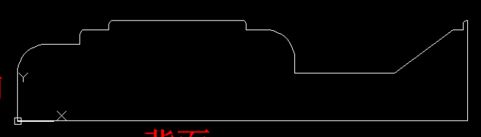
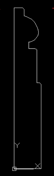
Crown molding contour: The left side of the contour faces the inside of the cabinet, the right side faces the outside of the cabinet, and the bottom point of the top line contour is the outermost point at the bottom (as shown in the figure below);
Crown molding contour: The left side of the contour faces the inside of the cabinet, the right side faces the outside of the cabinet, and the bottom point of the top line contour is the outermost point at the bottom (as shown in the figure below);
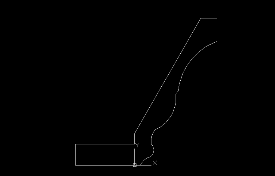
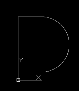
2. Toekick molding contour: The left side of the contour faces the inside of the cabinet, the right side faces the outside of the cabinet, and the origin is the lower left point of the contour (as shown in the figure below);
3. Front and rear edge height contours: Only the front edge with modeling is needed for the water stop contour (as shown in the figure below).
Front edge height contour
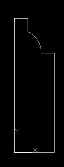
Rear edge height contour
4. Light rail molding contour: The left side of the contour faces the inside of the cabinet, the right side faces the outside of the cabinet, and the origin is the lower left point of the contour (as shown in the figure below).