Contents
I. Definition of 3D Partition Tool
II. How to Use 3D Partition Tool
I. Definition of 3D Partition Tool
The 3D model partition tool is a tool that cuts the model into smaller modules, which facilitates the conversion of the original model into a parameterized model during the parametric modeling process. It can only cut 3D uploaded models.
II. How to Use 3D Partition Tool
-
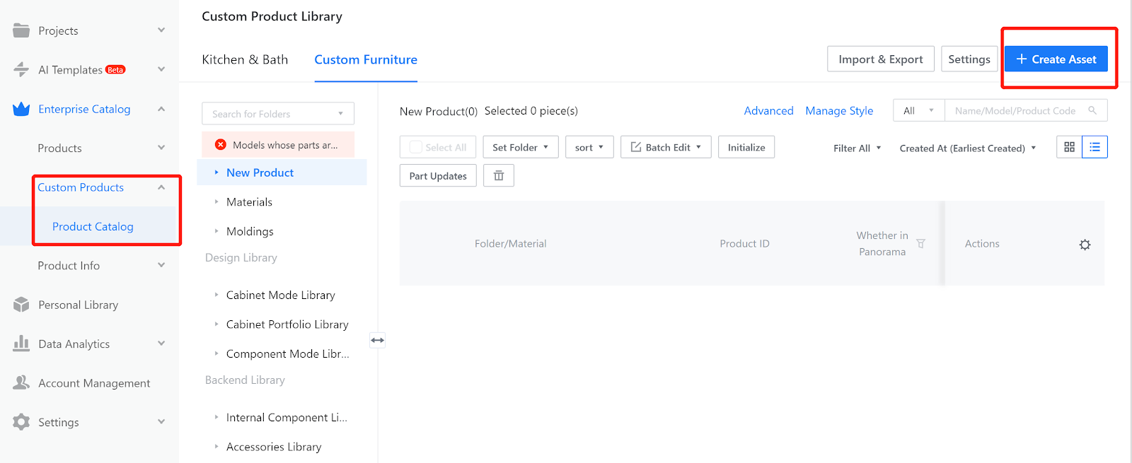
Enter the workspace-Custom Products-Product Catalog-Create Asset
Enter the workspace-Custom Products-Product Catalog-Create Asset
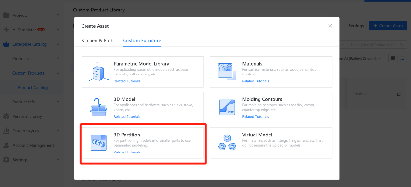
2. Select 3D Partition.
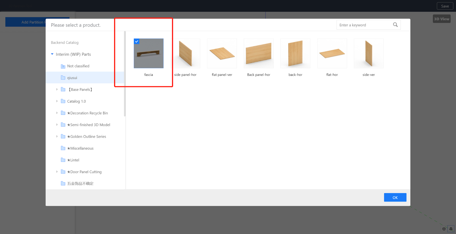
3. Select the model to be cut - confirm.
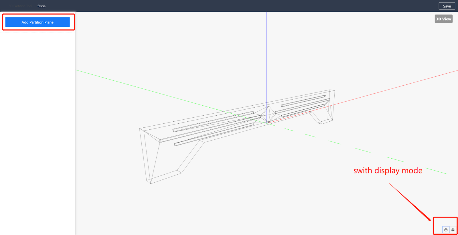
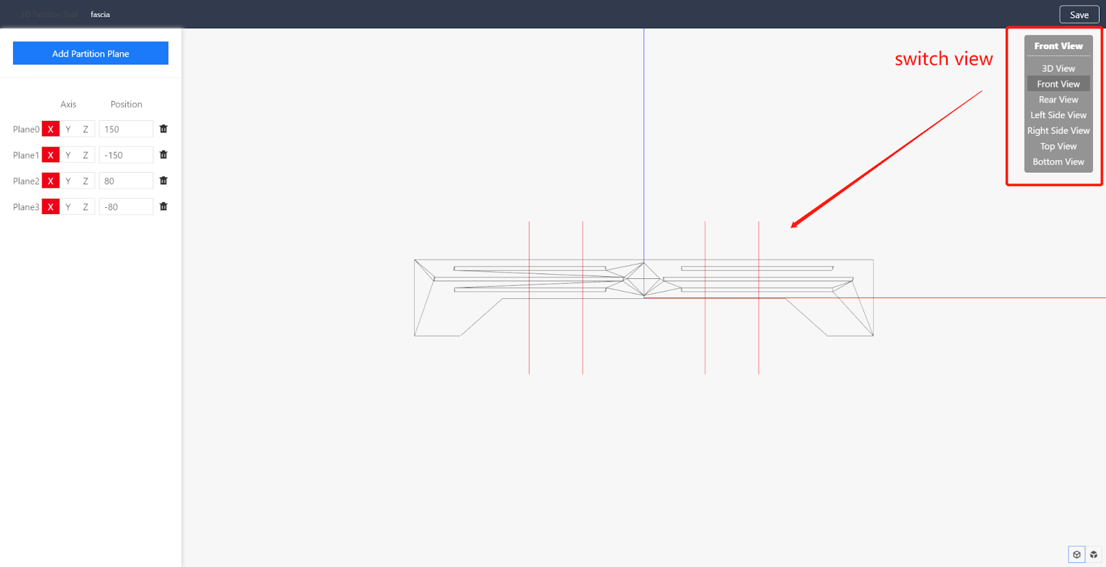
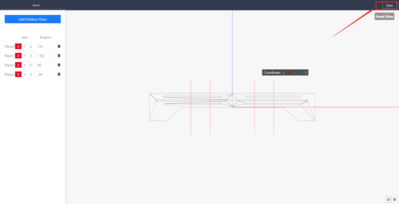
4. Enter the partition interface, and select the appropriate view orientation on the right side. Add a cutting plane on the left side, and select coloring mode and wire and frame mode in the lower right corner (the material color of the imported model is fixed by the system, and there is no need to worry about the model material transformation).
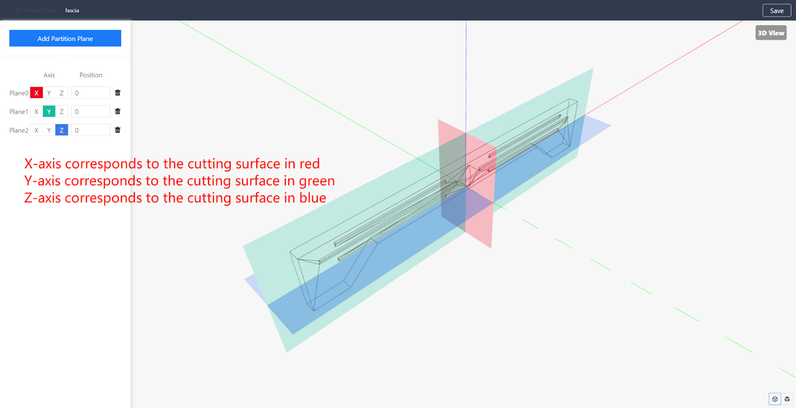
5. Add a partition plane and move it to the appropriate position. The cutting plane is generated perpendicular to the direction axis. For example, if the X axis is selected, it means that the cutting surface is generated perpendicular to the X axis. (Up to 9 cutting planes can be added.)
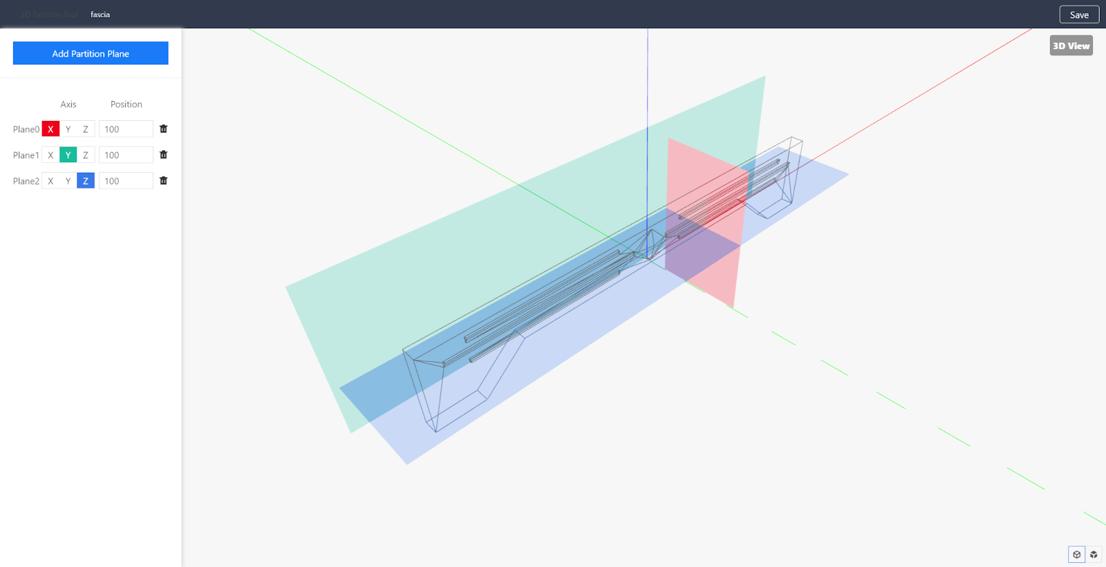
6. Set the position of the partition plane. The position can be input with positive and negative values. A positive number means that the cutting plane moves in the positive direction of the quadrant, and a negative number means that the cutting plane moves in the negative direction of the quadrant.
7. Take the cutting door panel as an example.
8. After adding the partition plane, click "Save" in the upper right corner, and select a directory to save the cutting model.
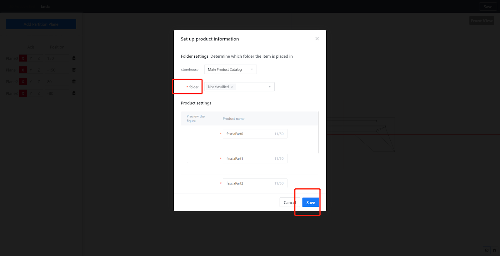
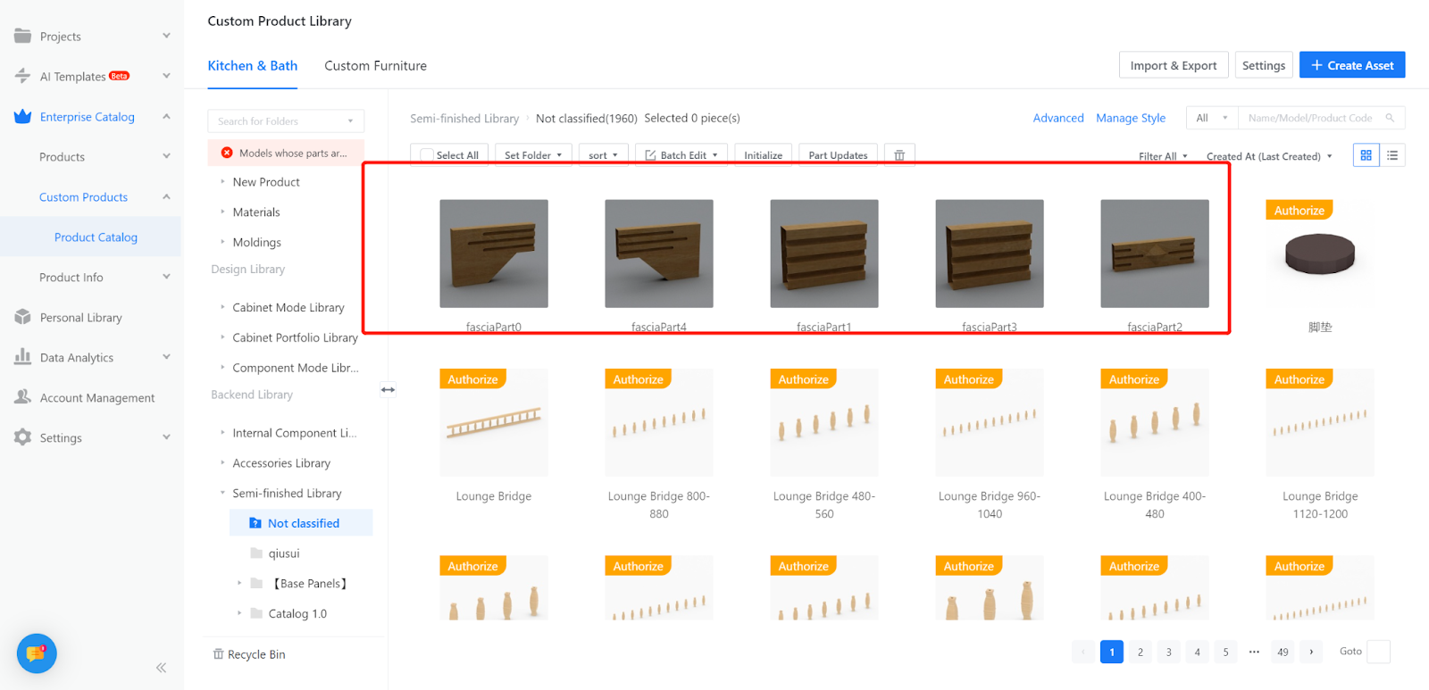
9. Enter the workspace - Custom Products-Product Catalog, find the saved directory file library, wait for rendering and conversion, and then it can be used.