Contents
I.Function Definition
II.Representation and Position
III.Meaning of the Model Rectangular Bound
IV.Purpose of the Model Rectangular Bound
V.Distinctions in Function
VI.Attributes of the Model Rectangular Bound
I.Function Definition
Whenever a model is created in the editor, a rectangular bound is automatically added, which serves as the model rectangular bound.
II.Representation and Position
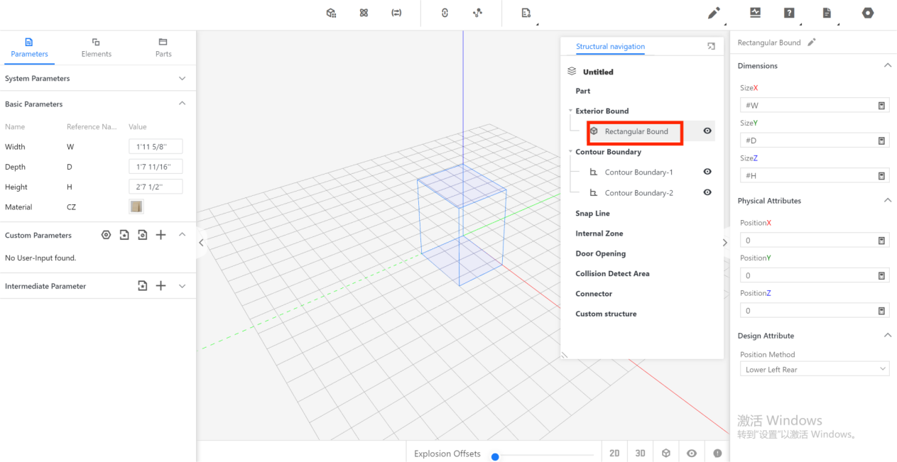
After creating a model, the visual representation of the model rectangular bound can be seen in the blue cube wireframe within the editor. The position of the model rectangular bound can be found within the structure navigation on the right side, under the model rectangular bound.
III.Meaning of the Rectangular Bound
It establishes a virtual framework for setting the size of the model.
IV.Purpose of the Model Rectangular Bound
It is used in front-end tools to achieve snapping or adaptation based on the recognized size.
V.Distinctions in Function
In cabinet mode, the model rectangular bound is used for snapping between cabinets, with the face of the model rectangular bound being snapped (the tool only recognizes the bound size, not the actual model size). In part models, the model rectangular bound is mainly used for adaptation, where the size of the model rectangular bound changes during adaptation.
VI.Attributes of the Model Rectangular Bound
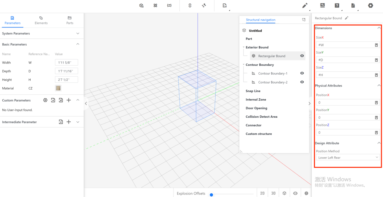
By left-clicking on the rectangular bound within the structure navigation, the attributes of the model rectangular bound are displayed on the right.
The attributes include physical attributes and other attributes. The physical attributes represent the position of the model rectangular bound in the coordinate axis (XYZ), while the other attributes include the size of the model rectangular bound in the coordinate axis (size XYZ) and the position method. It is important to note that the position and size attributes of the model rectangular bound are not allowed to be modified and remain default.
The invocation position method includes two options: left-rear-bottom option and center point. The default option is left-rear-bottom option. The method is consistent with the modeling method, meaning if the model was built using the left-rear-bottom method, the method will also be left-rear-bottom, and if the model was built using the center point method, the method will be the center point as well.