Definition
Introduction to contour line operations involved in uploading and creating a parameterized border component for sliding doors:
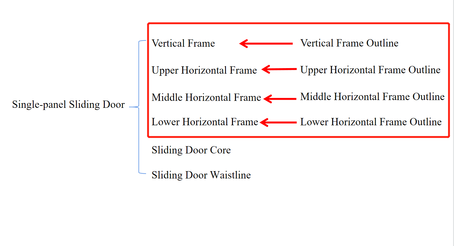
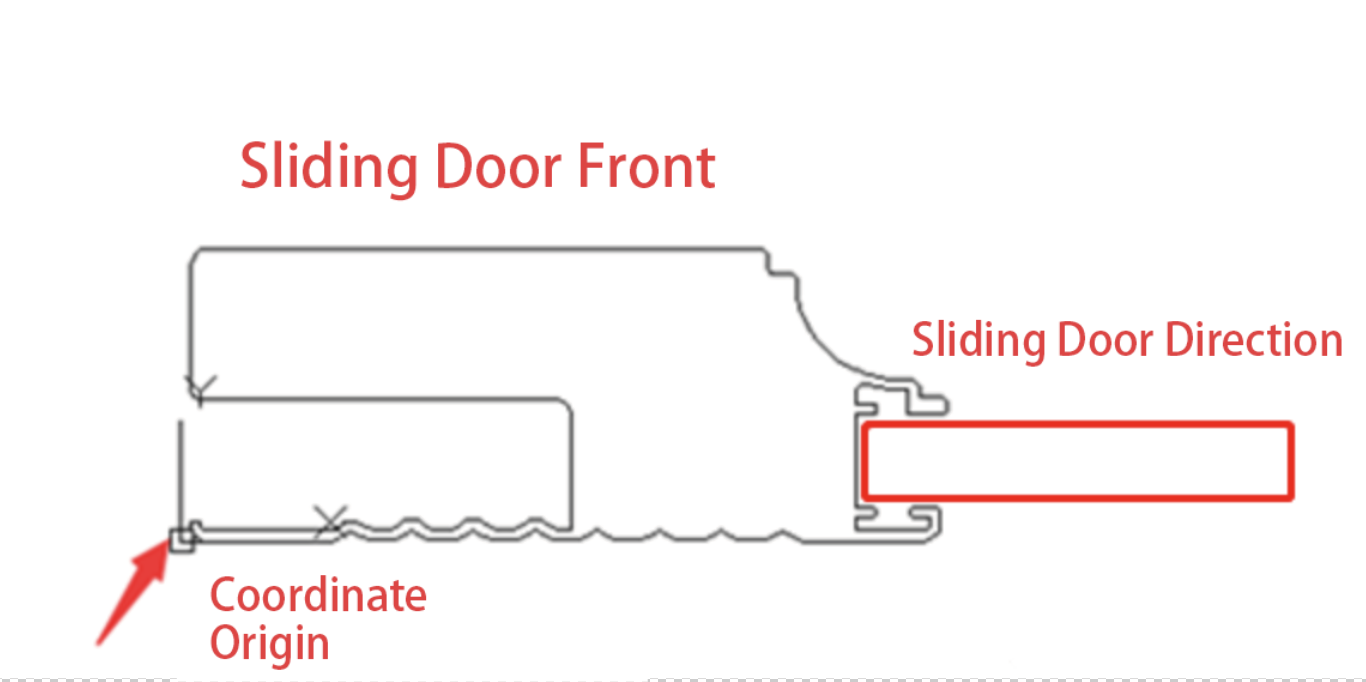
A single-panel sliding door is primarily composed of a border, door core, and waistline. The construction of the border involves developing the contour sections of each border. This also includes the development of the upper and lower guide rails for the sliding door using similar techniques. Therefore, it is crucial to understand the various parameters of these contour sections.
-
Vertical frame parameter expression and the meaning of notch parameters, as well as considerations when uploading vertical frames
Vertical frame parameter expression and the meaning of notch parameters, as well as considerations when uploading vertical frames
-
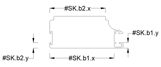
In the example diagram, the vertical frame section is shown. The vertical frame is divided into door core notches and horizontal frame notches.
In the example diagram, the vertical frame section is shown. The vertical frame is divided into door core notches and horizontal frame notches.
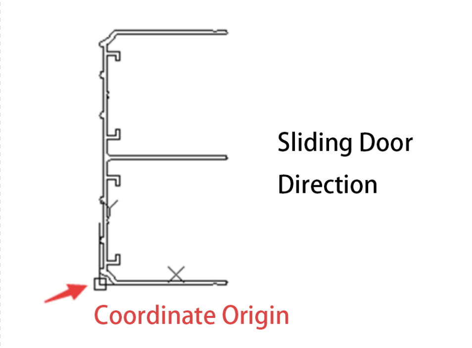
1.2 The placement direction of the vertical frame outline on the CAD drawing is as shown in the above figure:
1.3 Door core notch: Used to calculate the dimensions of the door core and define its position.
Horizontal frame notch: Used to calculate the dimensions of the horizontal frame and define its position.
Calling method for the door core notch:
- X-axis direction: `#SK.b1.x`
- Y-axis direction: `#SK.b1.y`
Calling method for the horizontal frame notch:
- X-axis direction: `#SK.b2.x`
- Y-axis direction: `#SK.b2.y`
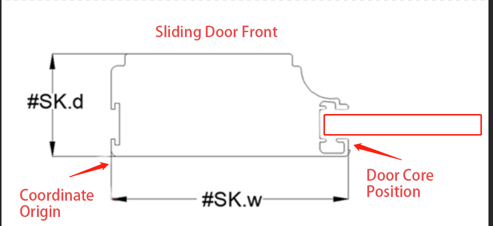
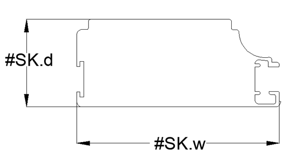
1.4 In the editor, the parameters representing the size of the vertical frame outline are as follows:
- `#SK.d` represents the thickness of the vertical frame outline.
- `#SK.w` represents the width of the vertical frame outline.
These variables are system defaults and do not require creating new ones.
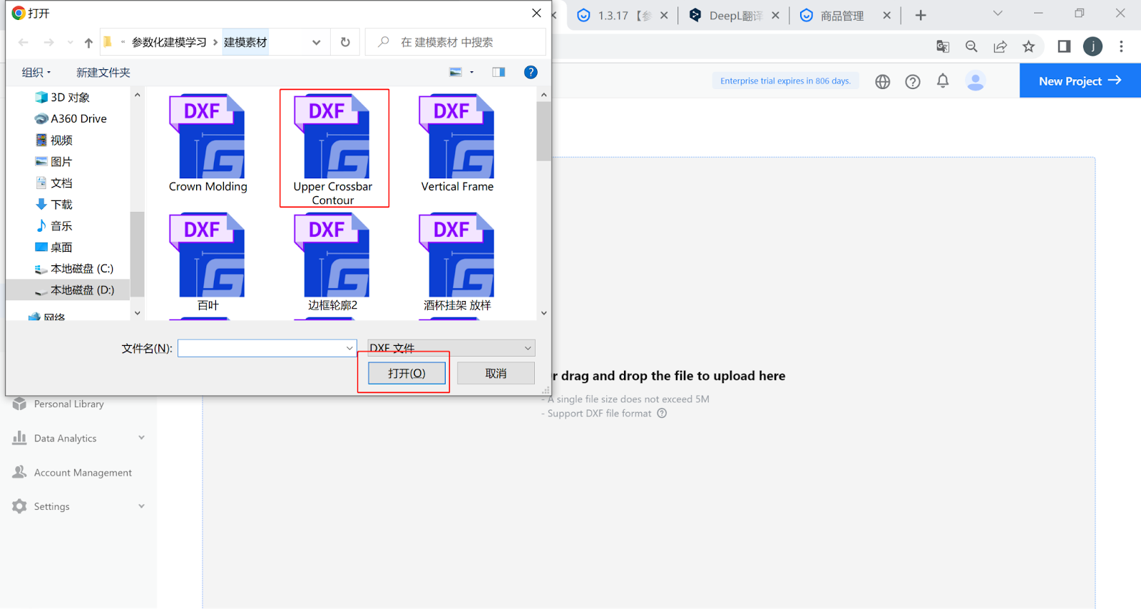
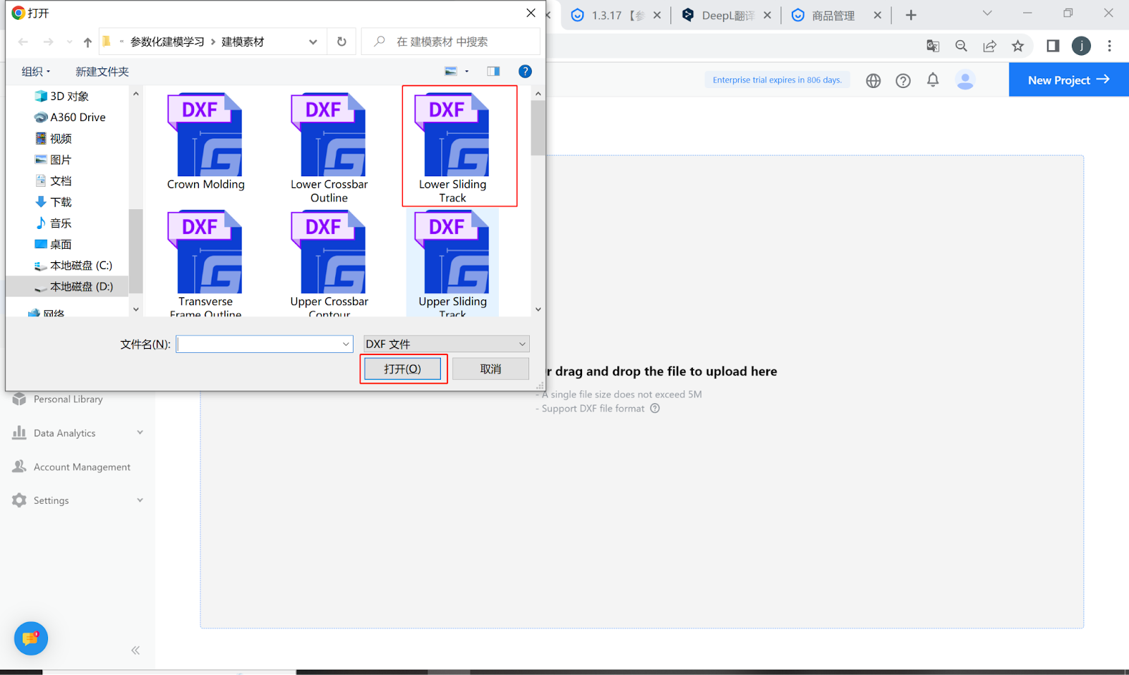
1.5 Upload the vertical frame outline by selecting the completed vertical frame outline file. The method for creating the outline is described in the outline line production requirements.
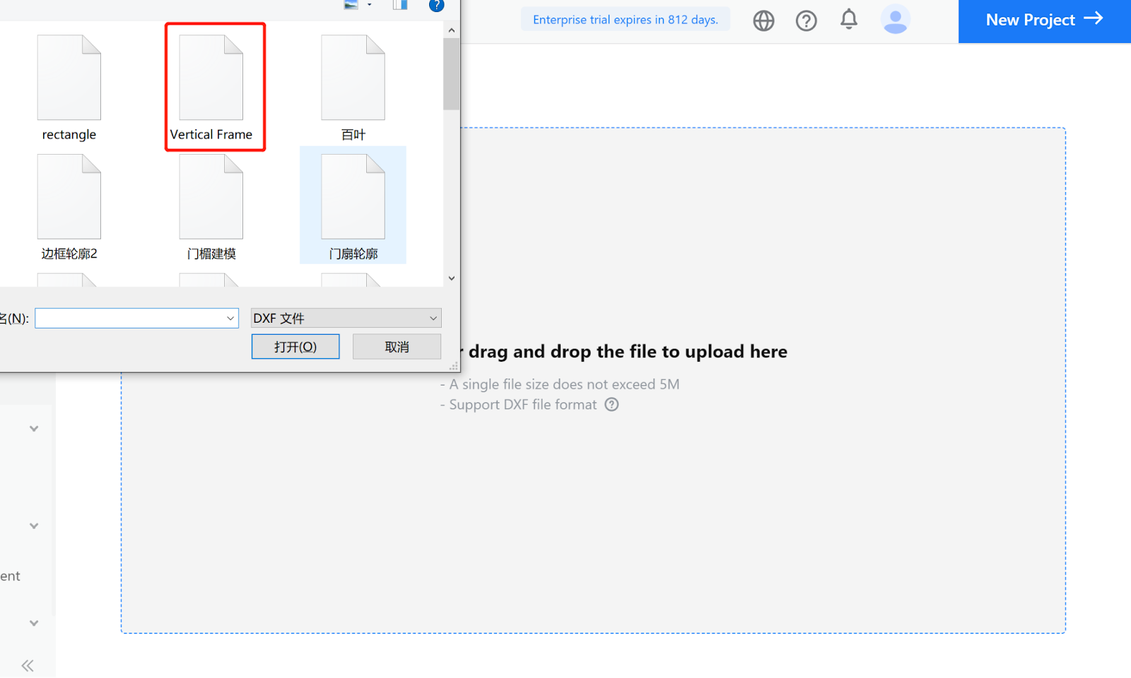
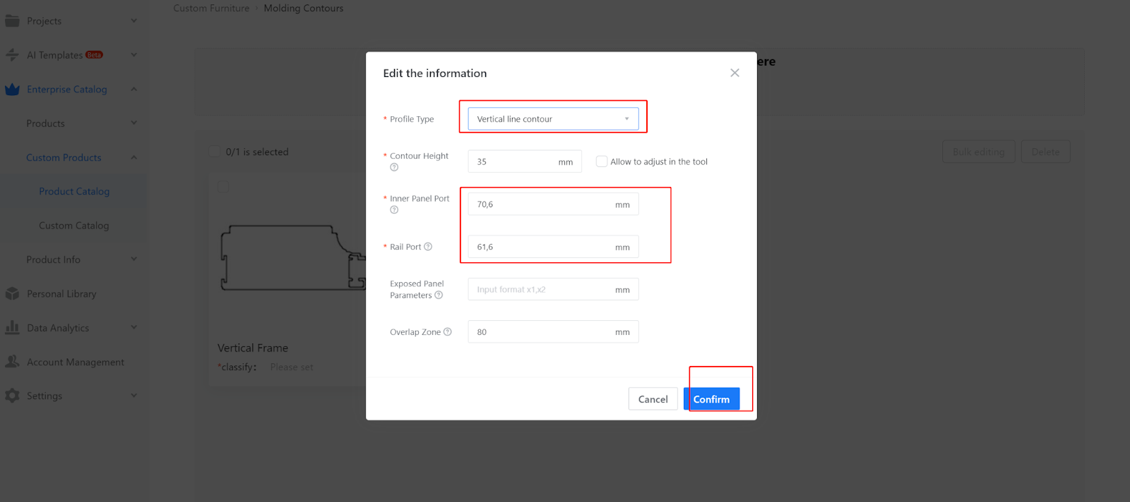
1.6 When uploading the vertical frame, select the line profile as the vertical frame outline. Fill in the corresponding values for the door core notch and horizontal frame notch by measuring them.
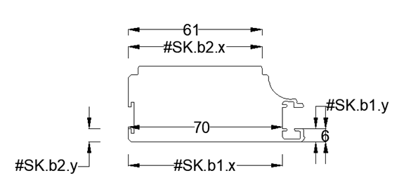
Door core notch: `#SK.b1.x`, `#SK.b1.y`
Horizontal frame notch: `#SK.b2.x`, `#SK.b2.y`
Note: These parameters represent the actual dimensions measured on the drawing. Different profiles may have different corresponding notch parameters.
-
Description of the upper horizontal frame parameters, the meaning of bayonet parameters, and precautions for uploading the upper horizontal frame
Description of the upper horizontal frame parameters, the meaning of bayonet parameters, and precautions for uploading the upper horizontal frame
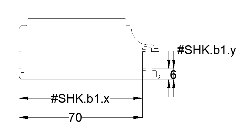
2.1 The upper crossbar only has core checkpoints.
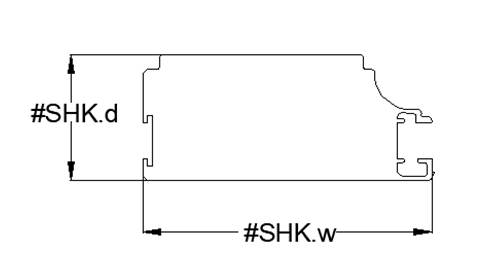
2.2 The placement direction of the upper crossbar outline on the CAD drawing is as shown in the figure
2.3 Core Checkpoint: It is used to calculate the dimensions of the core and define its position.
The method of calling the core checkpoint is as follows:
In the X-axis direction: #SHK.b1.x
In the Y-axis direction: #SHK.b1.y
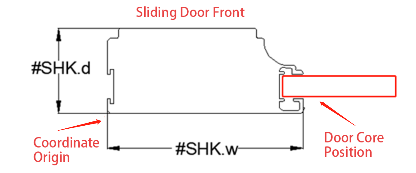
2.4 The parameters in the editor representing the size of the upper crossbar outline are as follows:
- #SHK.d represents the thickness of the upper crossbar outline.
- #SHK.w represents the width of the upper crossbar outline.
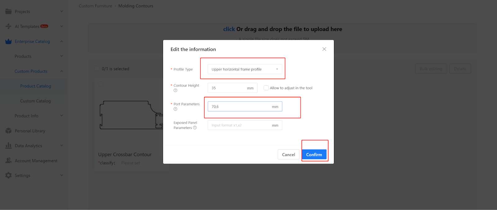
2.5 When uploading the upper crossbar contour, select the completed upper crossbar outline (the method of creating the outline is described in the contour production requirements).
2.6 When uploading the upper crossbar, select the line type as "Upper Crossbar contour" and fill in the corresponding checkpoint parameter values by measurement.
Checkpoint parameters: #SHK.b1.x, #SHK.b1.y
-
Description of the lower horizontal frame parameters, meaning of bayonet parameters, precautions when uploading the lower horizontal frame
Description of the lower horizontal frame parameters, meaning of bayonet parameters, precautions when uploading the lower horizontal frame
3.1 As shown in the example diagram, the lower crossbar section consists only of core checkpoints. The checkpoints are used to calculate the dimensions of the core and define its position. The checkpoint parameters are set on each border of the lower crossbar.
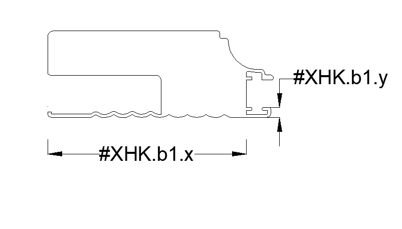
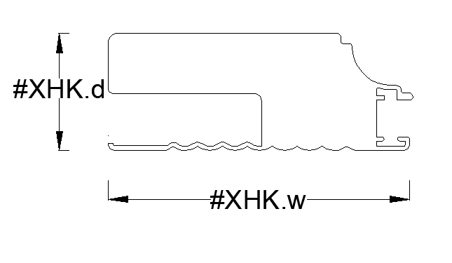
3.2 The placement direction of the lower horizontal outline on the CAD drawing is shown in the figure
3.3 Core Checkpoint: It is used to calculate the dimensions of the core and define its position.
The method of calling the core checkpoint is as follows:
In the X-axis direction: #XHK.b1.x
In the Y-axis direction: #XHK.b1.y
3.4 The parameters in the editor representing the size of the lower crossbar outline are as follows:
- #XHK.d represents the thickness of the lower crossbar outline.
- #XHK.w represents the width of the lower crossbar outline.
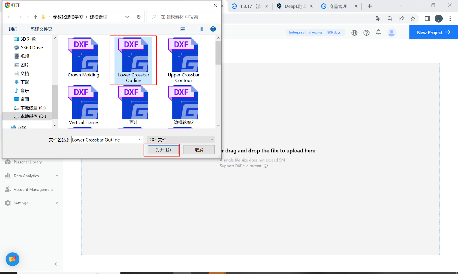
3.5 When uploading the lower crossbar outline, select the completed lower crossbar outline (the method of creating the outline is described in the outline production requirements).
3.6 When uploading the lower crossbar, fill in the corresponding values for the core checkpoint and select the line type as "Lower Crossbar contour."
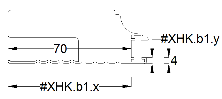
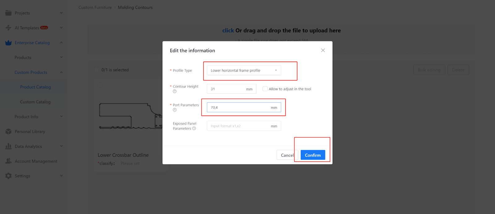
Checkpoint parameters: #XHK.b1.x, #XHK.b1.y
-
Description of horizontal frame parameters, meaning of bayonet parameters, precautions when uploading horizontal frame
Description of horizontal frame parameters, meaning of bayonet parameters, precautions when uploading horizontal frame
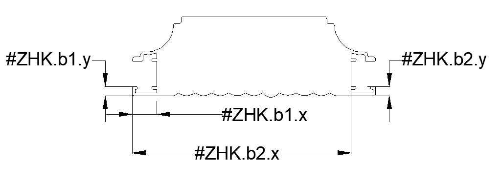
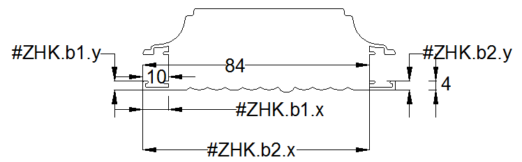
4.1 As shown in the example diagram, the middle crossbar section is divided into upper and lower checkpoints. These checkpoints are used to calculate the dimensions of the core and define its position. The checkpoint parameters are set on each border of the middle crossbar.

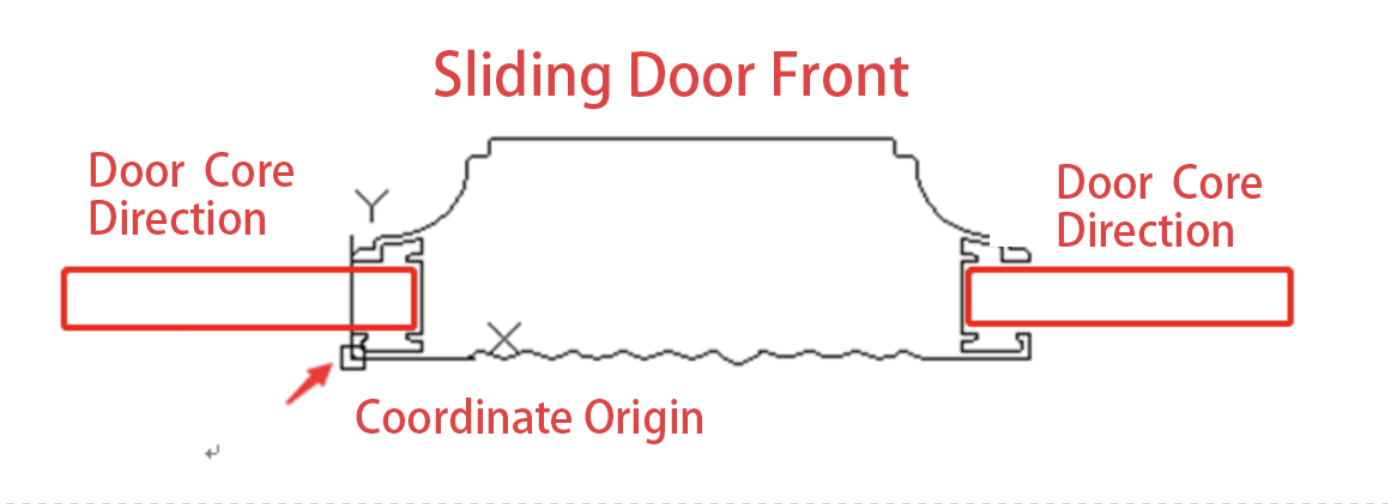
4.2 The placement direction of the outline of the middle horizontal frame on the CAD drawing is shown as follows:
4.3 Upper and lower checkpoints: Used to calculate the dimensions of the door core and define its position.
The calling method for the upper checkpoint on the transverse frame is as follows:
In the X-axis direction: #ZHK.b1.x
In the Y-axis direction: #ZHK.b1.y
The calling method for the lower checkpoint on the transverse frame is as follows:
In the X-axis direction: #ZHK.b2.x
In the Y-axis direction: #ZHK.b2.y
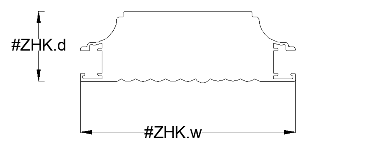
4.4 Parameters representing the size and shape of the transverse frame outline in the editor:
#ZHK.d represents the thickness of the transverse frame outline,
#ZHK.w represents the width of the transverse frame outline.
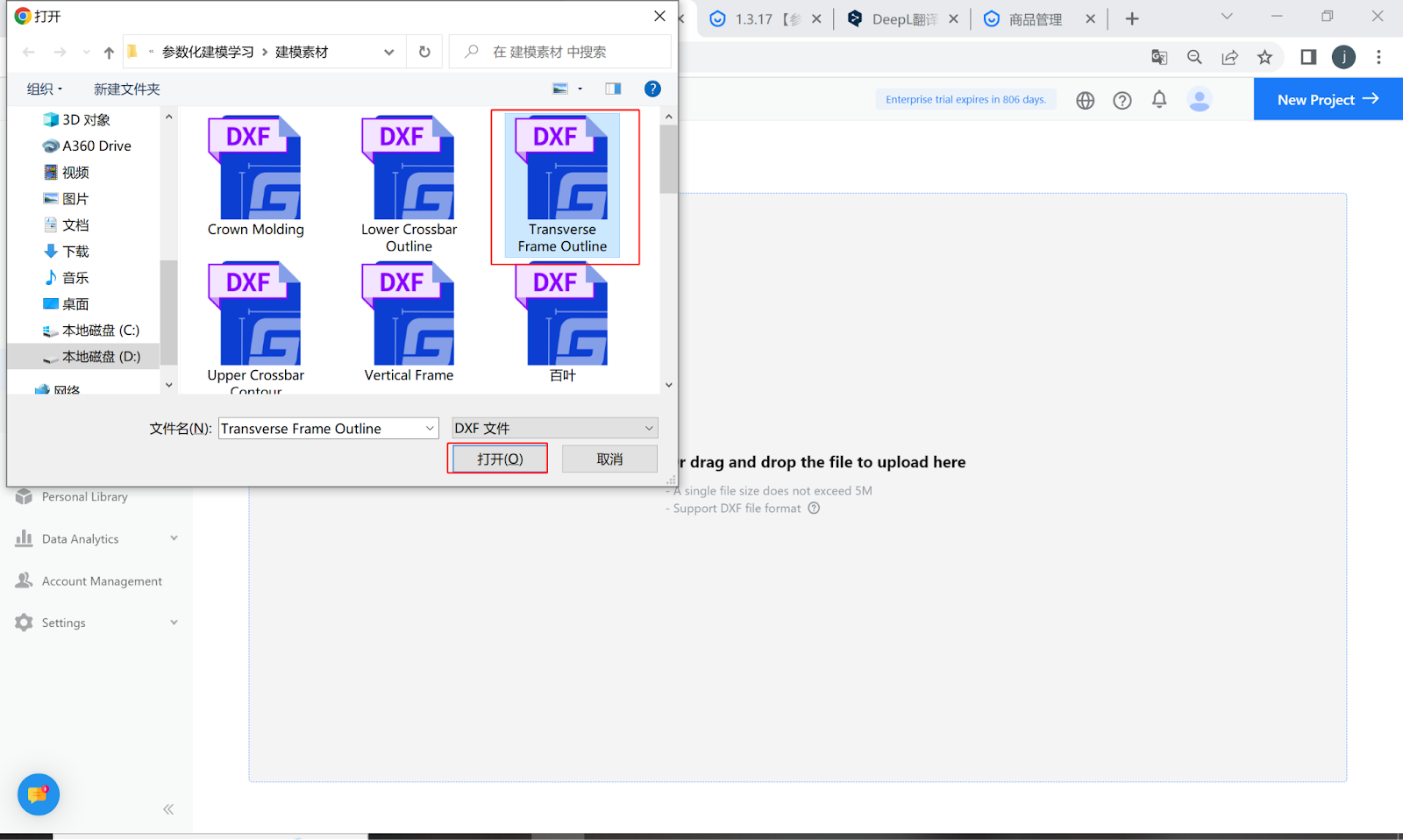
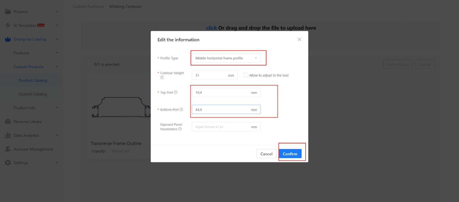
4.5 To upload the transverse frame outline, select the completed transverse frame outline (the method for creating the outline is explained in the contour line production requirements).
4.6 When uploading the transverse frame, fill in the corresponding values for the upper and lower checkpoints, and select the line type as "transverse outline."
Upper checkpoint: #ZHK.b1.x, #ZHK.b1.y
Lower checkpoint: #ZHK.b2.x, #ZHK.b2.y
-
Description of upper guide rail parameters, meaning of bayonet parameters, precautions when uploading upper guide rail
Description of upper guide rail parameters, meaning of bayonet parameters, precautions when uploading upper guide rail
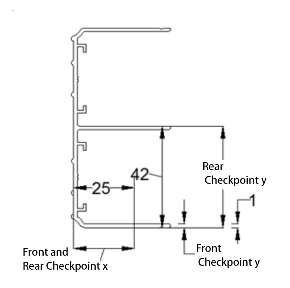
5.1 As shown in the diagram, the upper sliding track has a front checkpoint and a rear checkpoint (checkpoint: determines the position of the sliding door).
5.2 The placement direction of the upper sliding track outline on the CAD drawing is depicted in the diagram on the right.
5.3 The front and rear checkpoint dimensions in the X direction: Used to allocate space for the positioning of the pulleys. Please fill in the actual dimensions based on the size of the pulleys.
The front and rear checkpoint dimensions in the Y direction: Used to determine the position of the generated sliding door in the depth direction.
5.4 To upload the outline of the upper sliding track, select the completed outline of the upper sliding track (the method for creating the outline is explained in the contour line production requirements).
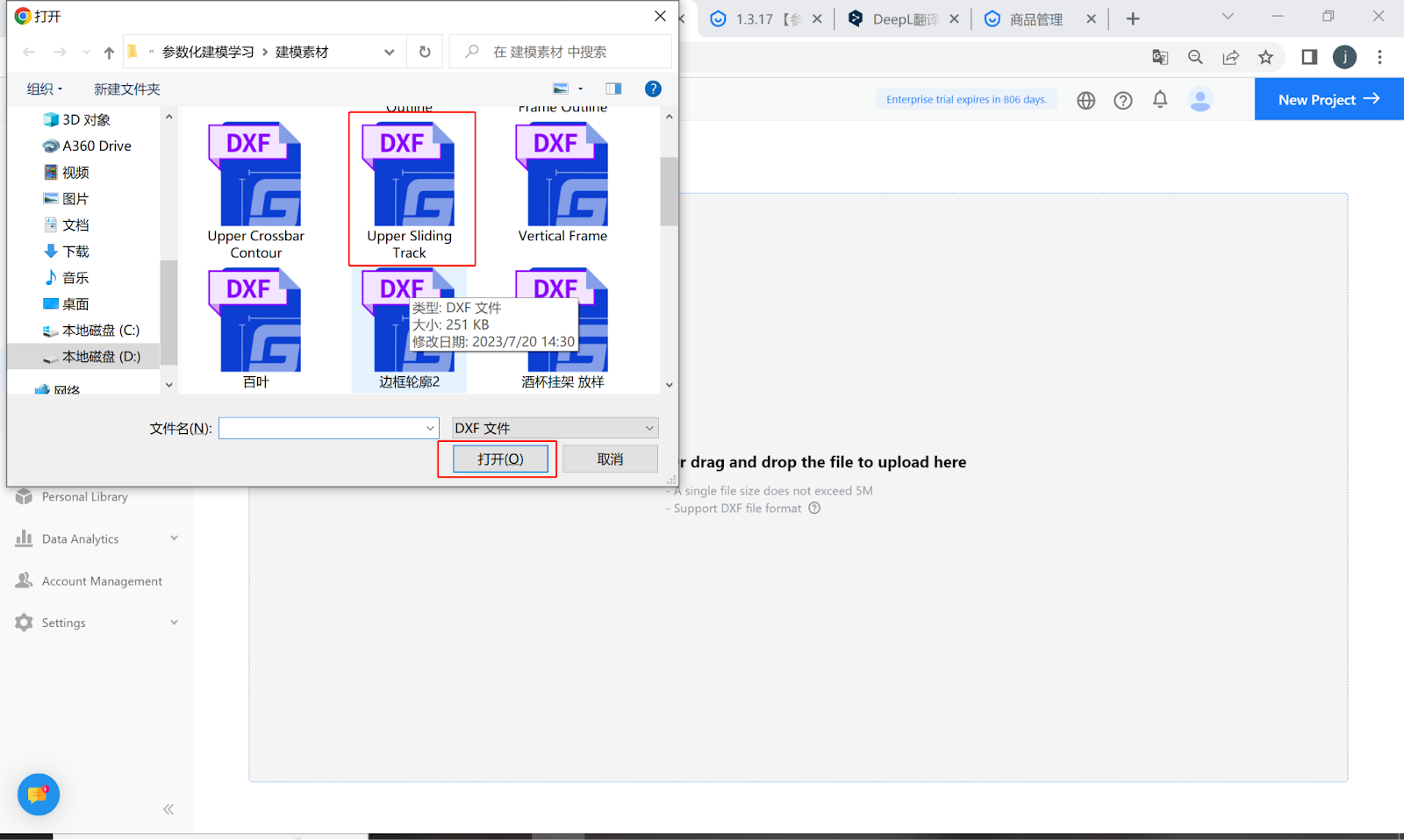
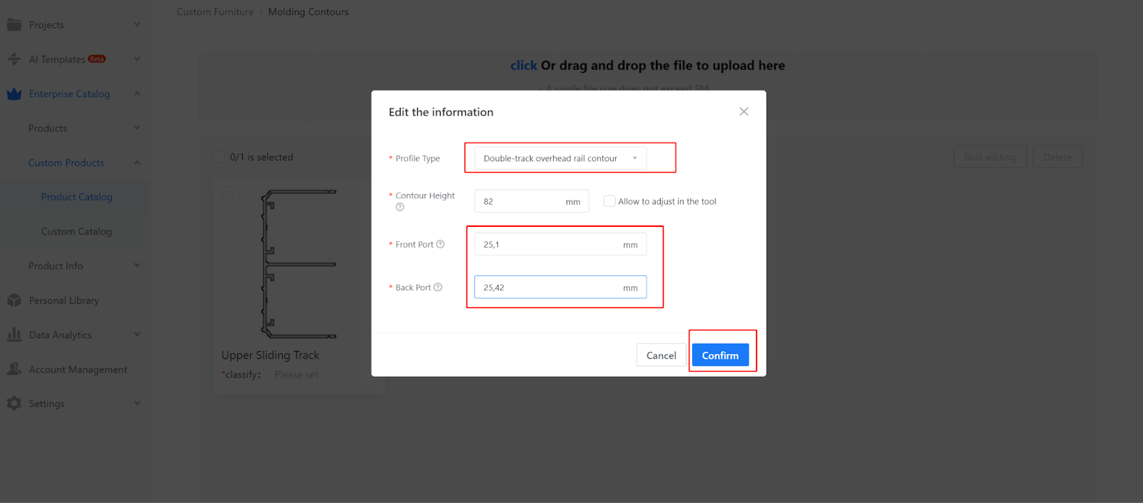
5.5 When uploading the upper sliding track, fill in the corresponding values for the front and rear checkpoints, and select the line type as "upper sliding track outline."
-
Slide rail parameter expression, and the meaning of bayonet parameter, precautions when uploading slide rail
Slide rail parameter expression, and the meaning of bayonet parameter, precautions when uploading slide rail
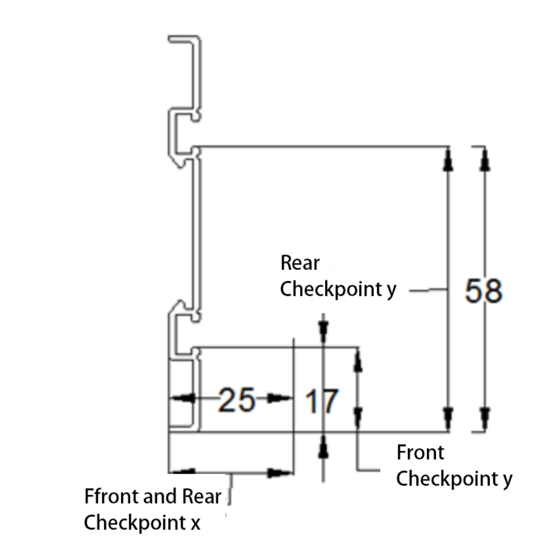
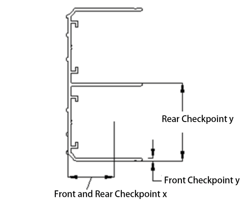
6.1 As shown in the diagram, the lower sliding track has a front checkpoint and a rear checkpoint (checkpoint: determines the position of the sliding door).
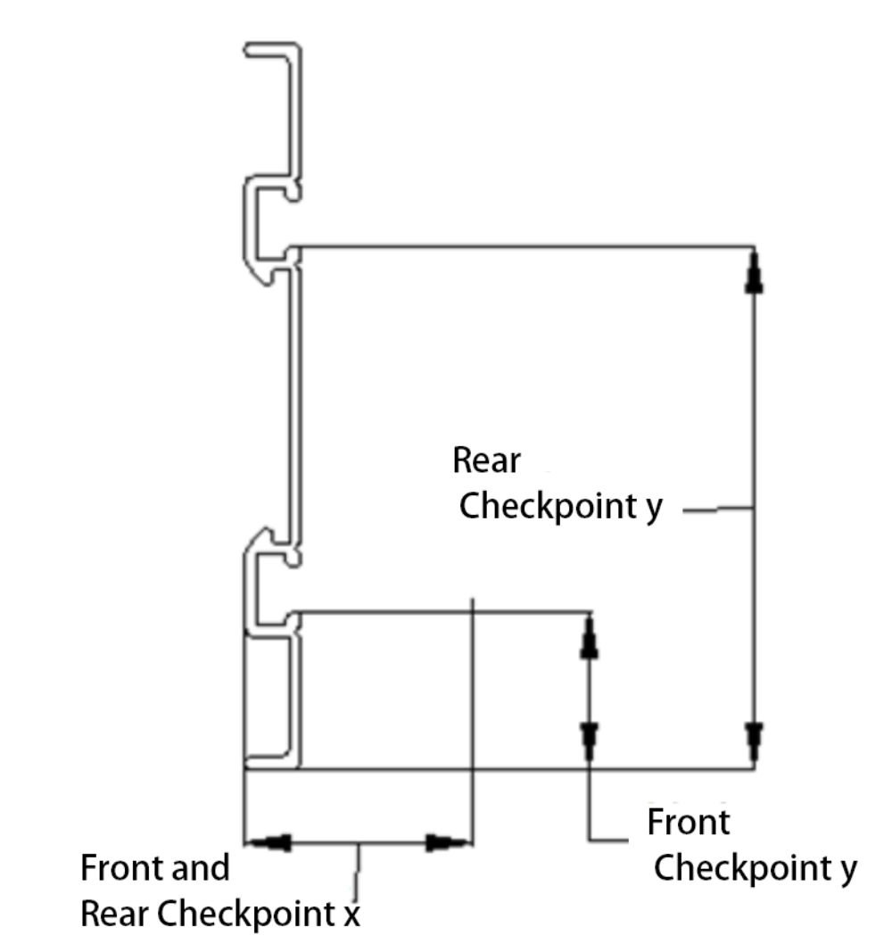
6.2 The placement direction of the glide rail outline on the CAD drawing is shown as follows:
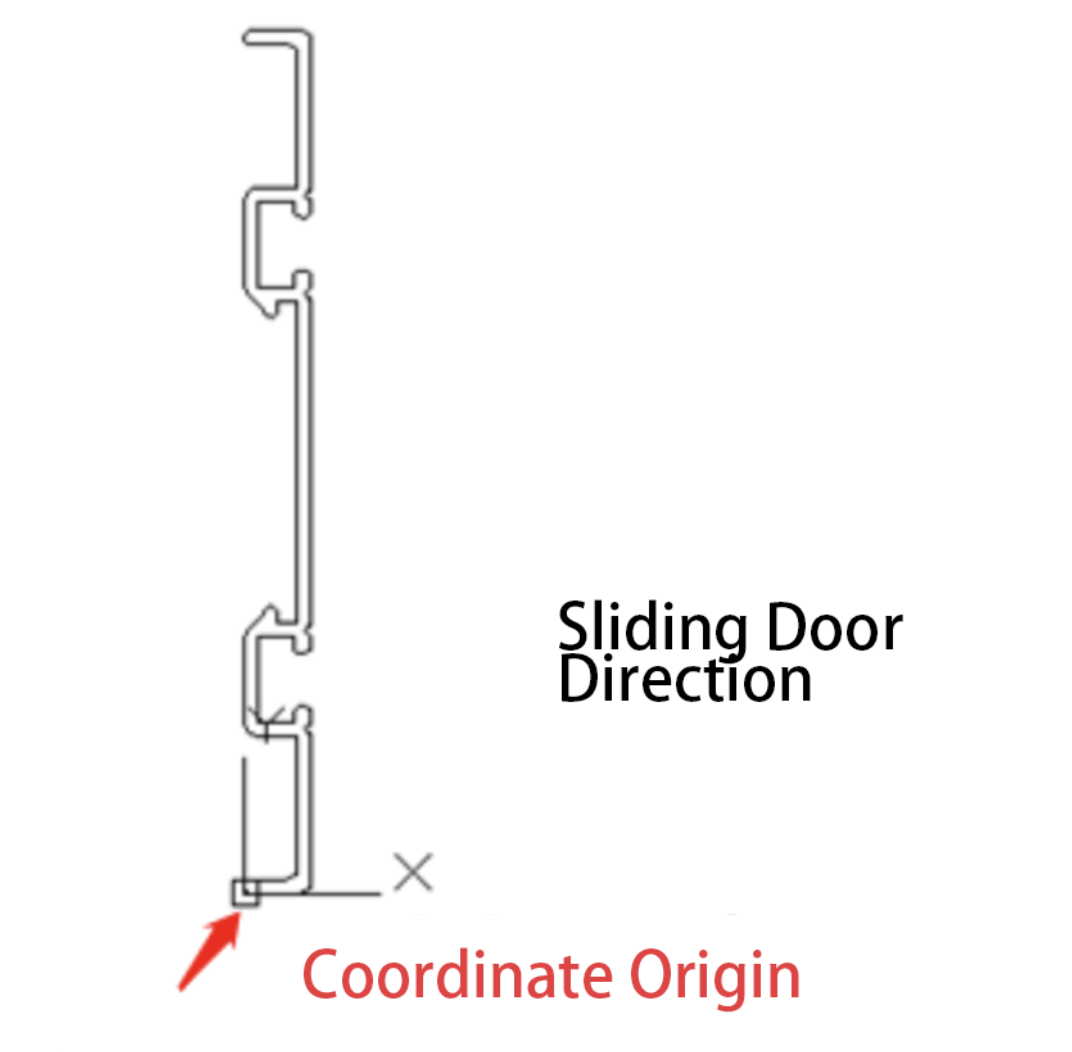
6.3 The front and rear checkpoint dimensions in the X direction: Used to allocate space for the positioning of the pulleys. Please fill in the actual dimensions based on the size of the pulleys.
The front and rear checkpoint dimensions in the Y direction: Used to determine the position of the generated sliding door in the depth direction.
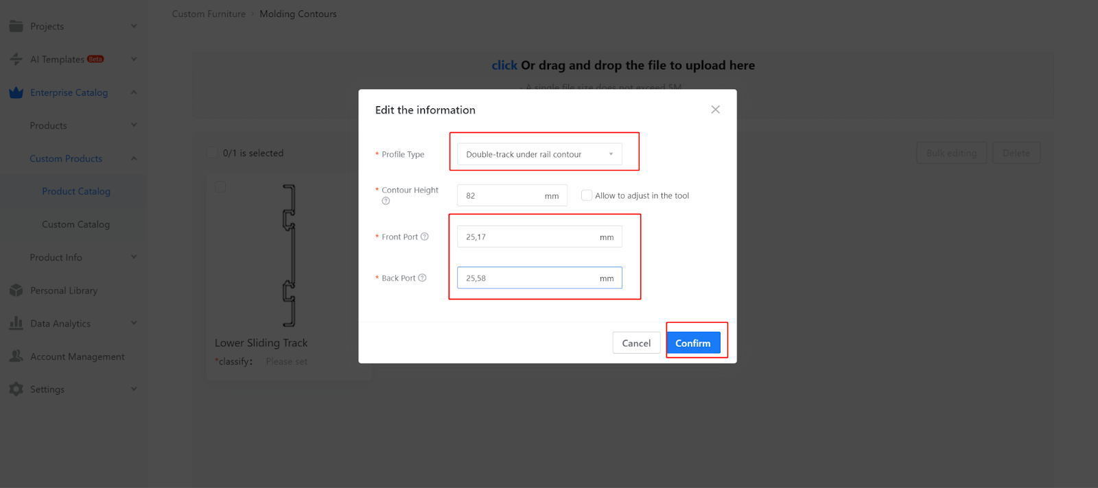
6.4 To upload the outline of the lower sliding track, select the completed outline of the lower sliding track (the method for creating the outline is explained in the contour line production requirements).
6.5 When uploading the lower sliding track, fill in the corresponding values for the front and rear checkpoints, and select the line type as "lower sliding track outline."