Definition
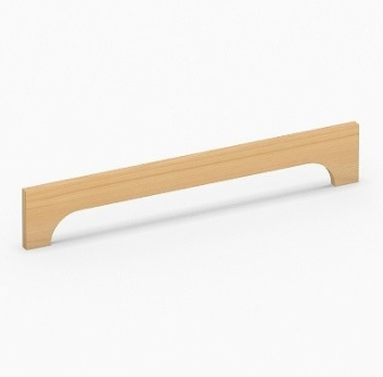
A Decorative Lintel Panel is a component that serves as a decorative element in the whole-house customization tool.
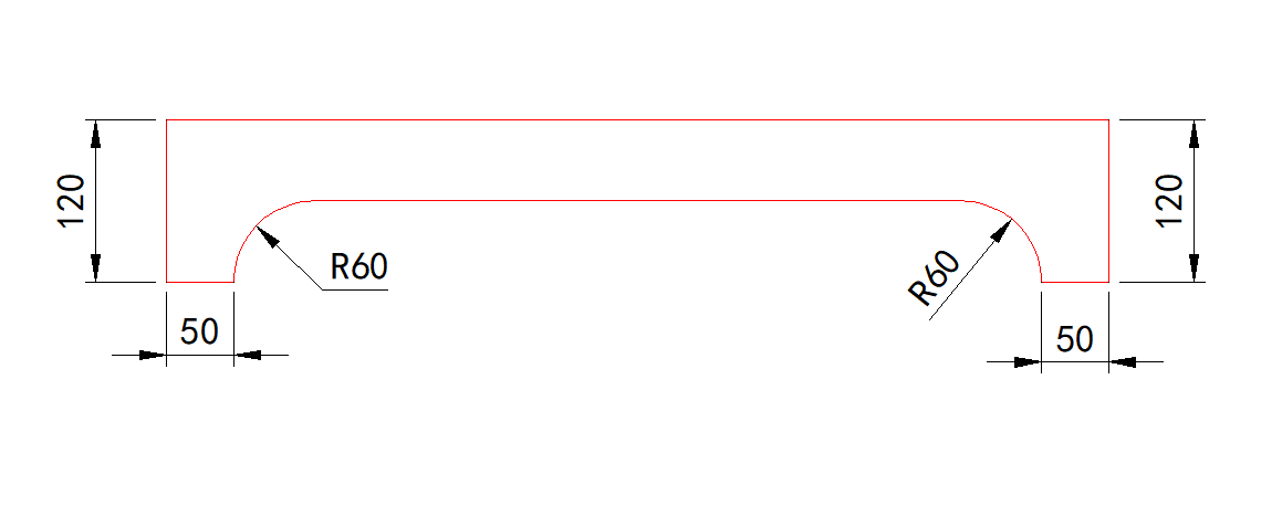
Taking the shape in the following figure as an example, let's create a model for a Decorative Lintel Panel.
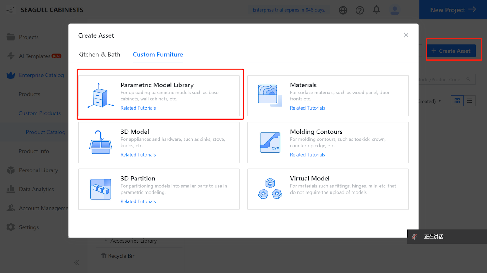
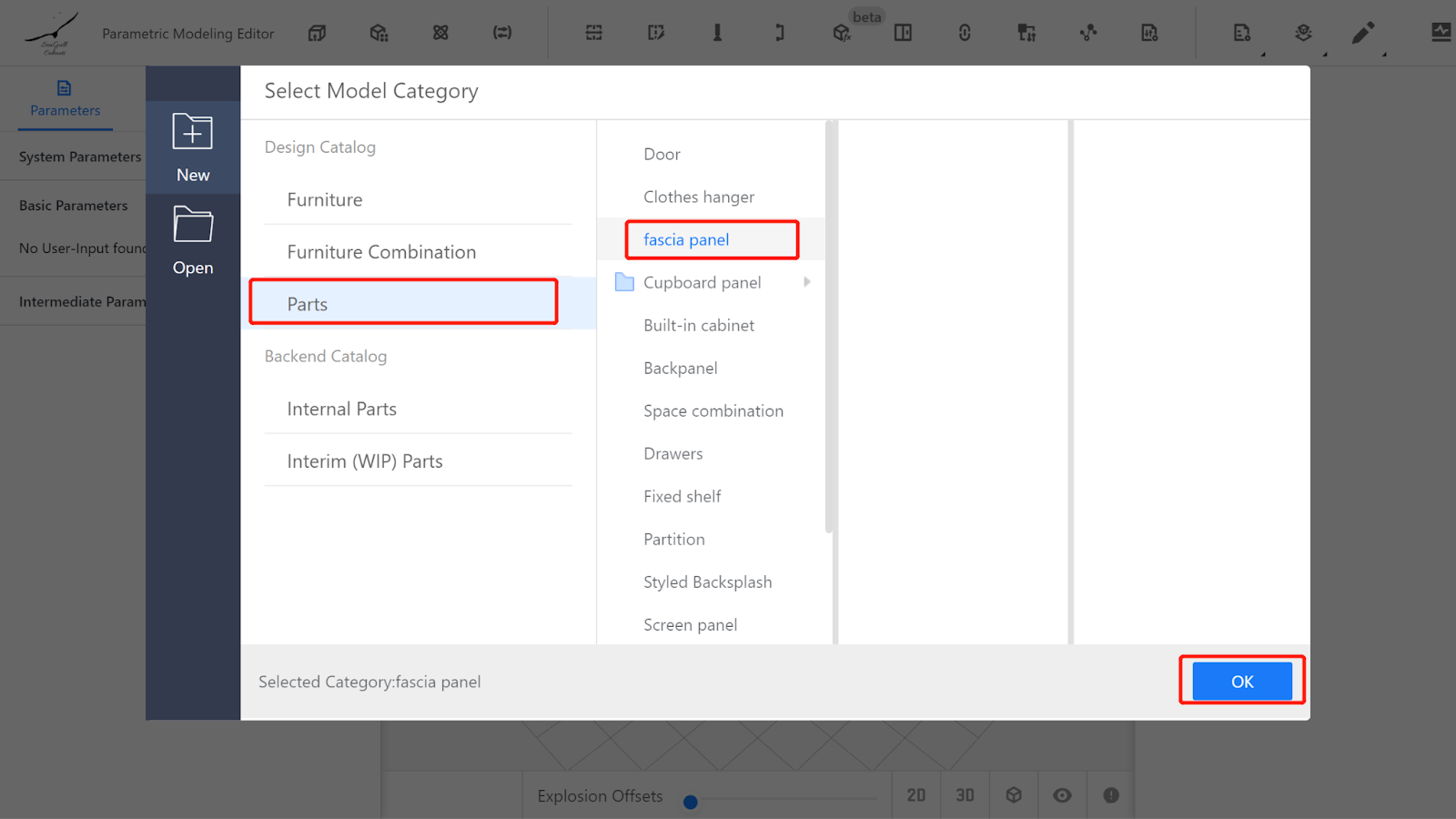
I. Creation Location
Custom Furniture—Create Asset—Parametric Model Library— New—
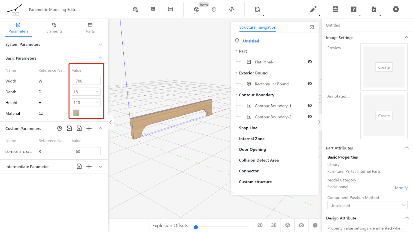
II. Parameter Configuration - Custom parameters
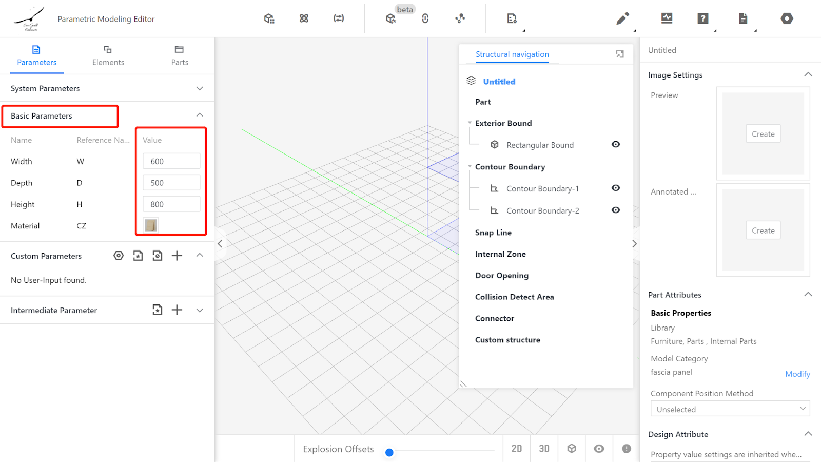
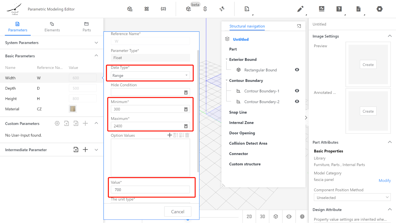
Width (W) - Represents the size of the Panel in the X-axis direction, with value type set as a range (e.g., range from 300 to 2400, current value is 700).
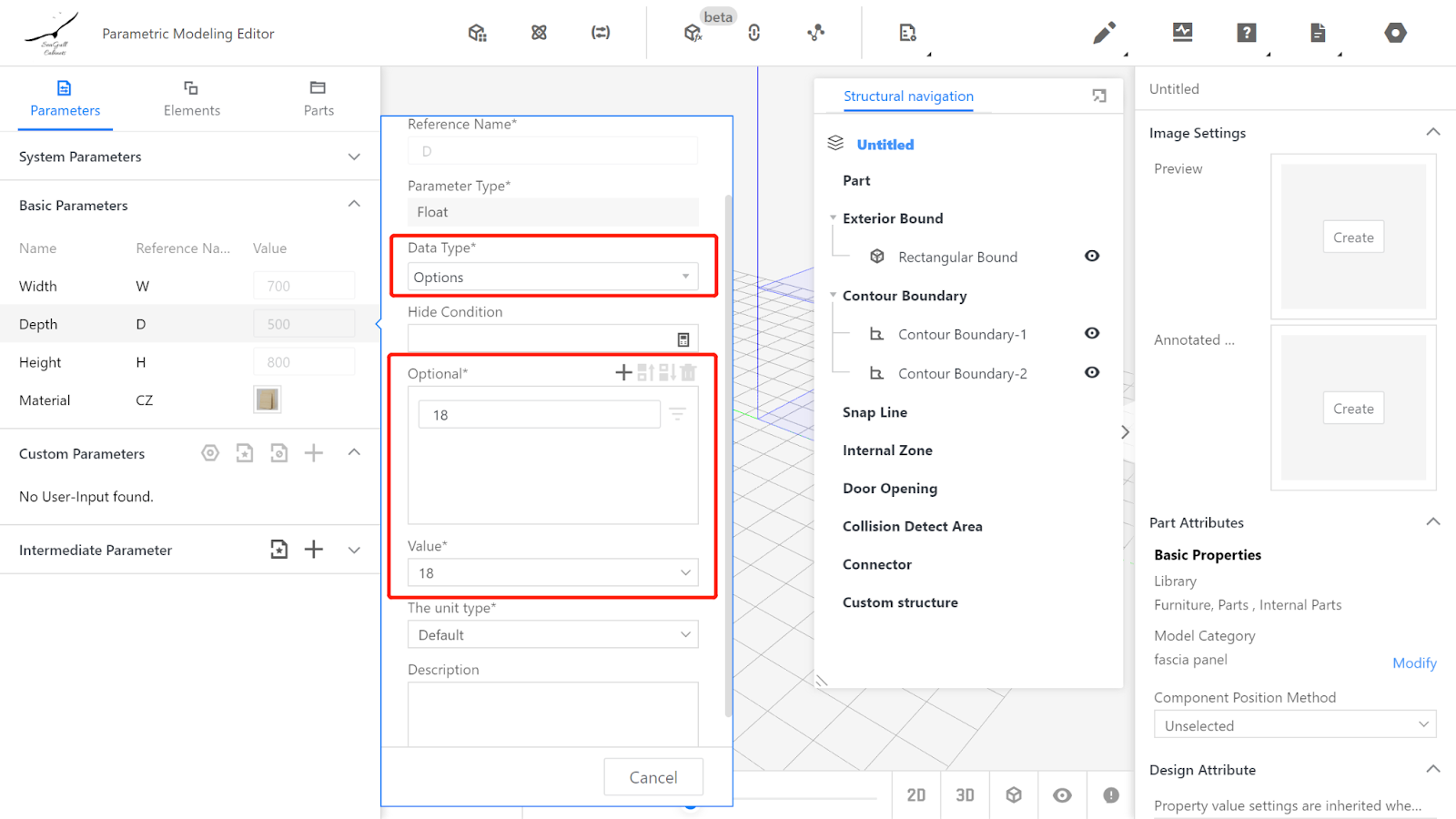
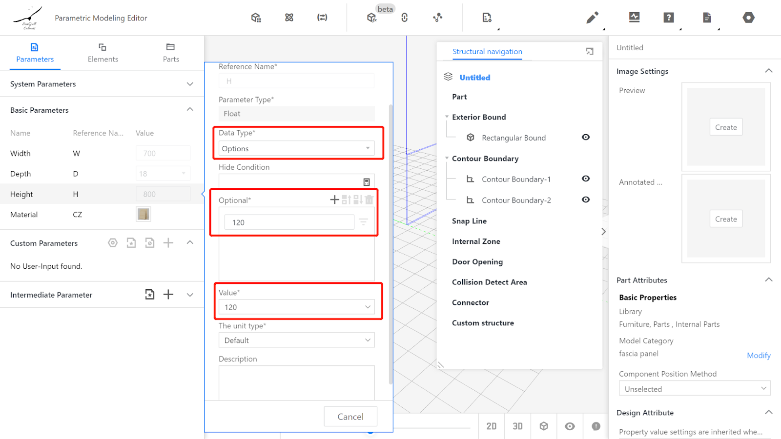
Depth (D) - Represents the size of the Panel in the Y-axis direction, with value type set as optional (e.g., optional values: 18, current value is 18).
Height (H) - Represents the size of the Panel in the Z-axis direction, with value type set as a range or optional (e.g., optional value: 120, current value is 120).
Material does not need to be changed, indicating that the default material will be used.
(Note: The range of parameter values mentioned above can be set based on actual process requirements and is not fixed.)
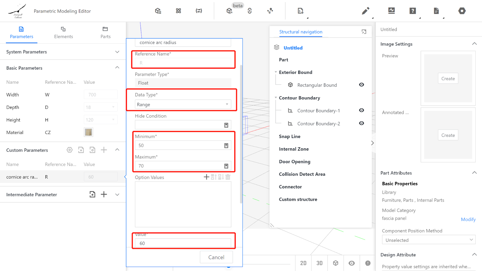
Creating an advanced parameter for controlling the size of the cornice arc, with reference name-R and value type as a range or optional (e.g., range from 50 to 70, current value is 60).
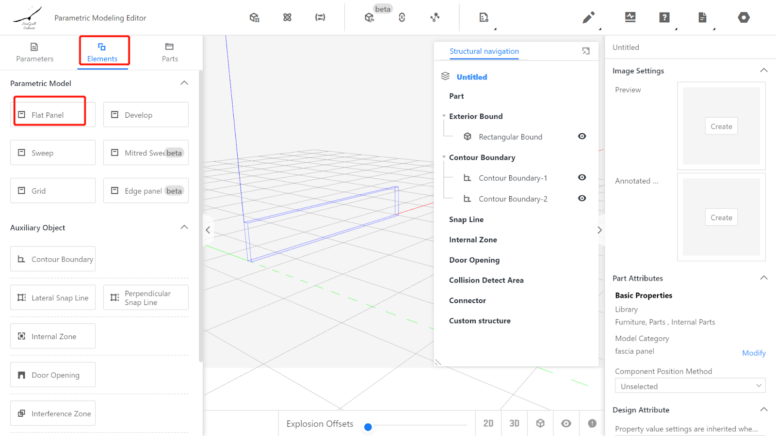
III. Calling the Flat Panel Component
Element Library - Parametric Model - Flat Panel
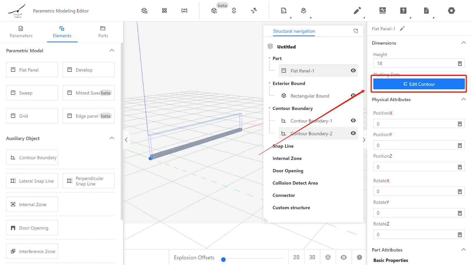
IV. Setting the Physical Properties of the Irregular Cuboid
Physical Properties - Edit contour
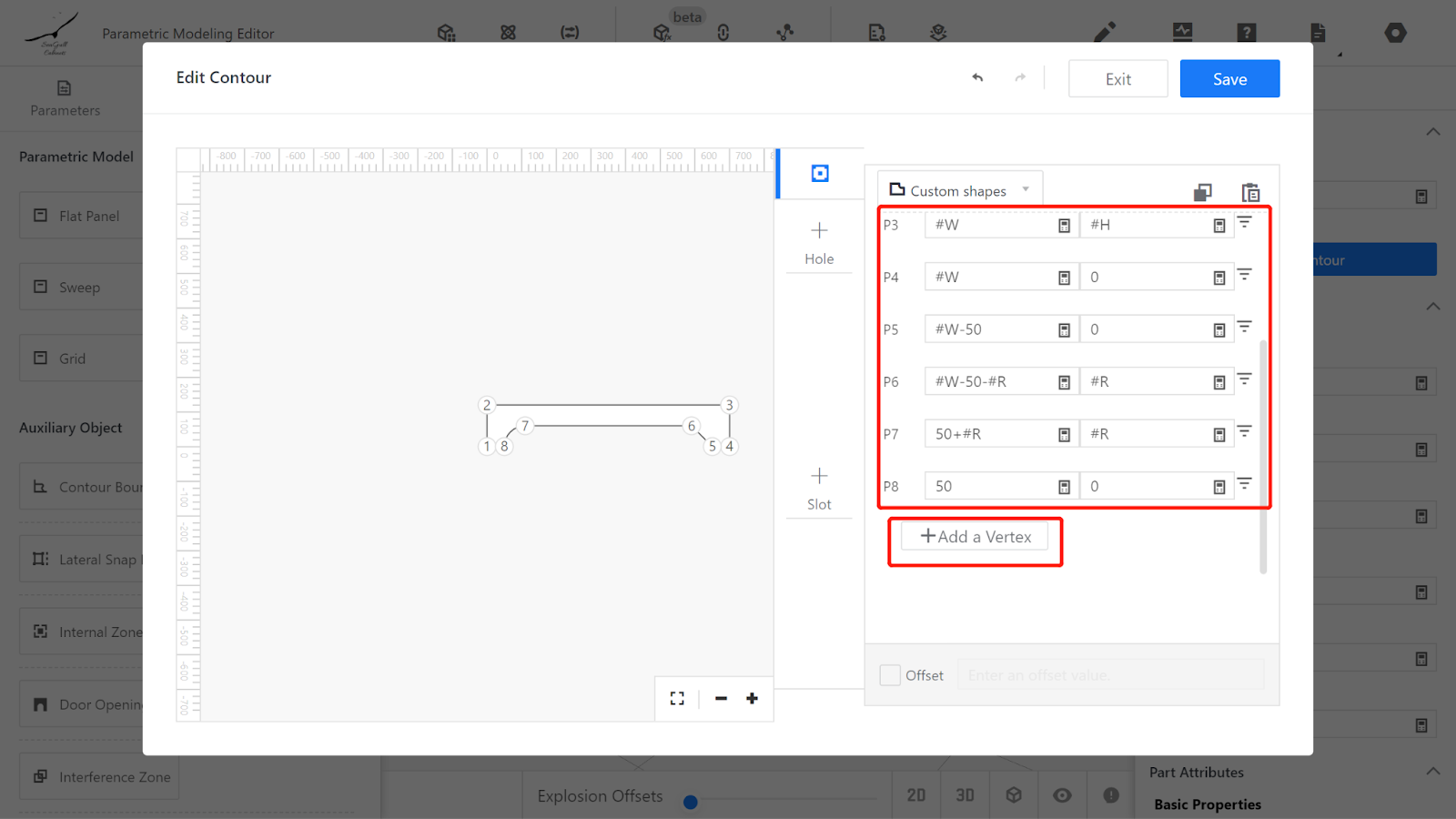
Insert Endpoints - Edit Endpoints, starting from the bottom-left point (0, 0), write down the position of each endpoint:
Point 1 (0, 0) Point 2 (0, #H)
Point 3 (#W, #H) Point 4 (#W, 0)
Point 5 (#W-50, 0) Point 6 (#W-50-#R, #R)
Point 7 (50+#R, #R) Point 8 (50, 0)
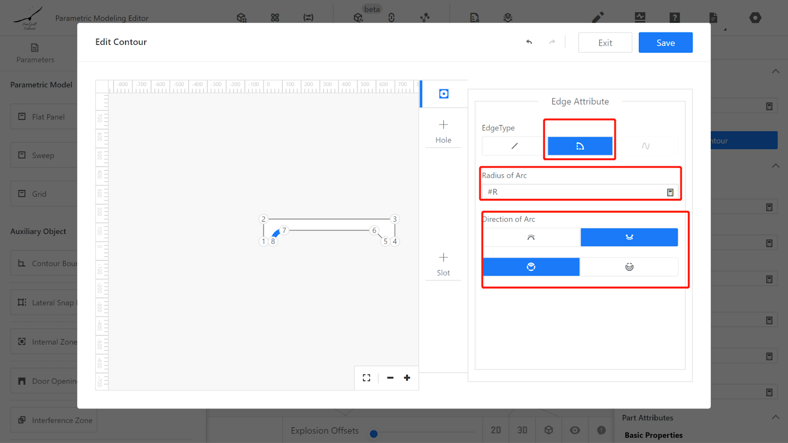
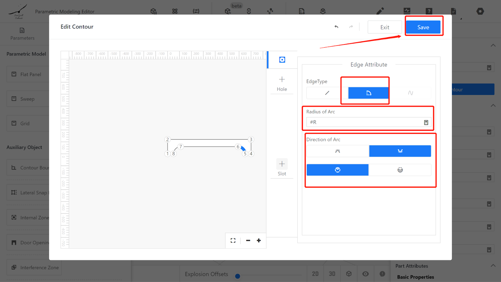
Change the segment types of lines 7-8 and 5-6 to arcs, with an arc radius of #R.
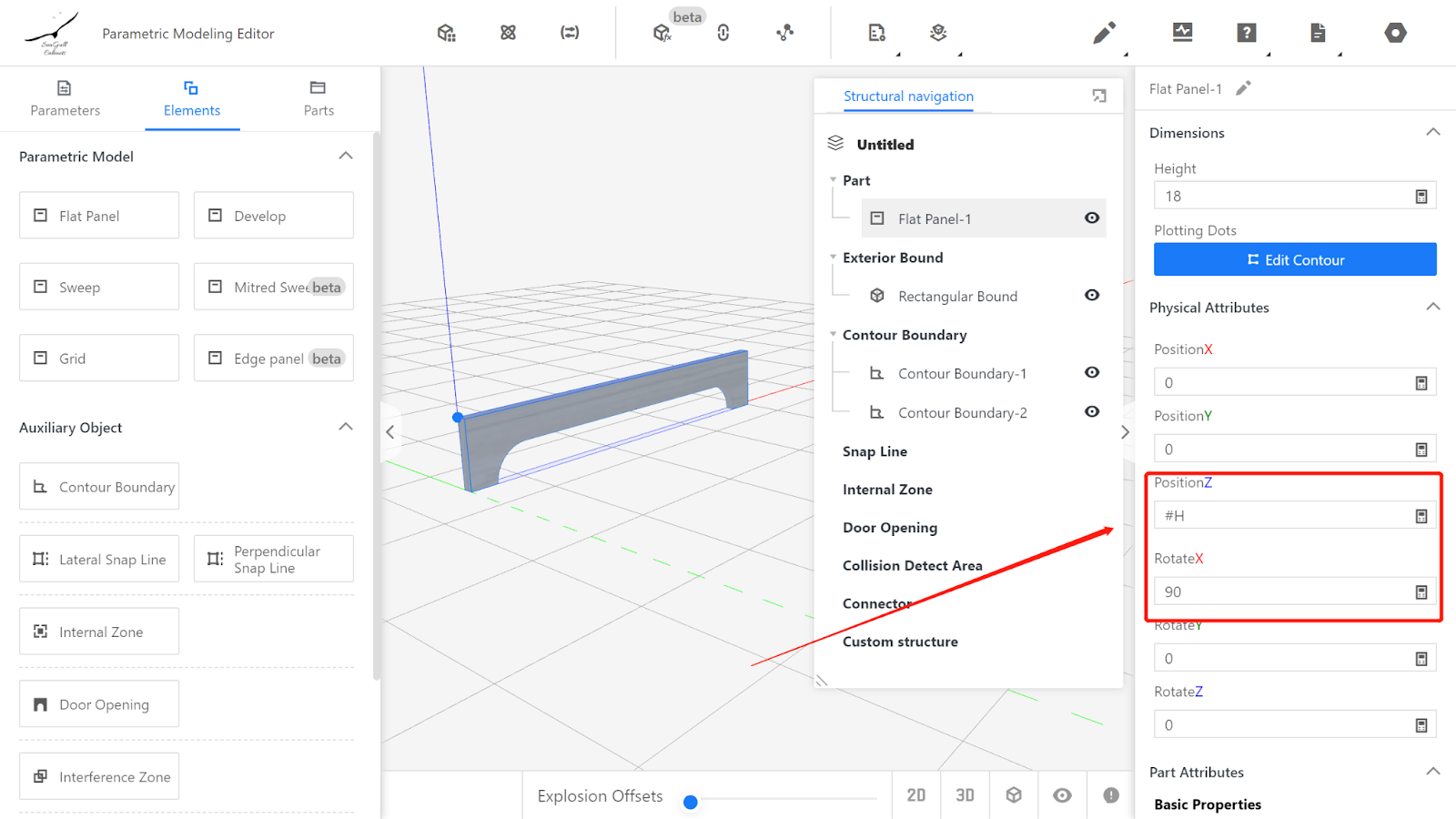
Adjust the position and rotation (to make the model appear within the frame): Position Z: #H, Rotation X: 90.
Setting System parameters
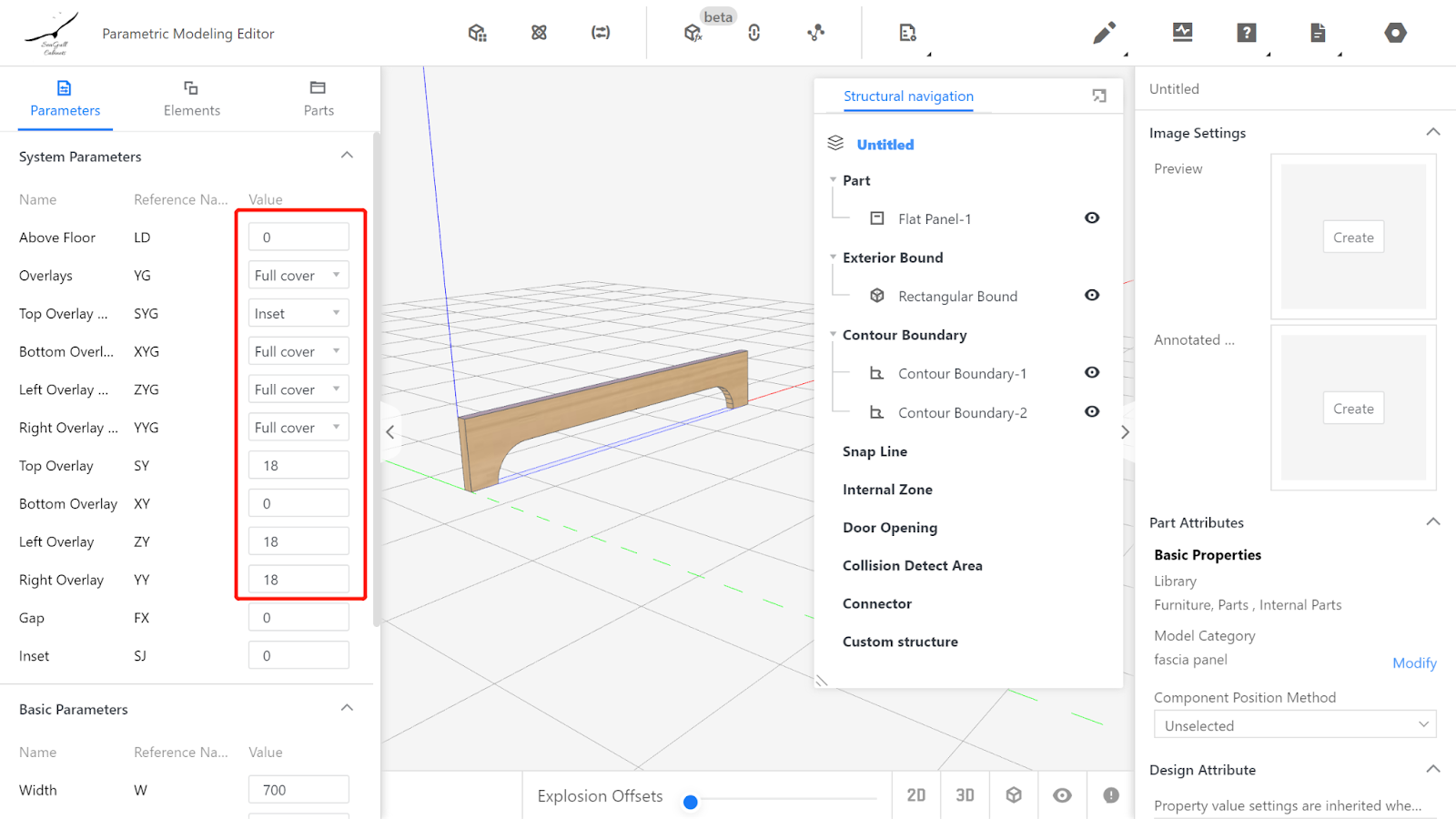
Currently, when the model is dragged out for use, it defaults to full coverage. Therefore, the overlay methods are as follows:
Top overlay: Full Coverage, Bottom overlay: Embedded, Left overlay: Full Coverage, Right overlay: Full Coverage.
Top overlay: 18, Bottom overlay: 0, Left overlay: 18, Right overlay: 18.
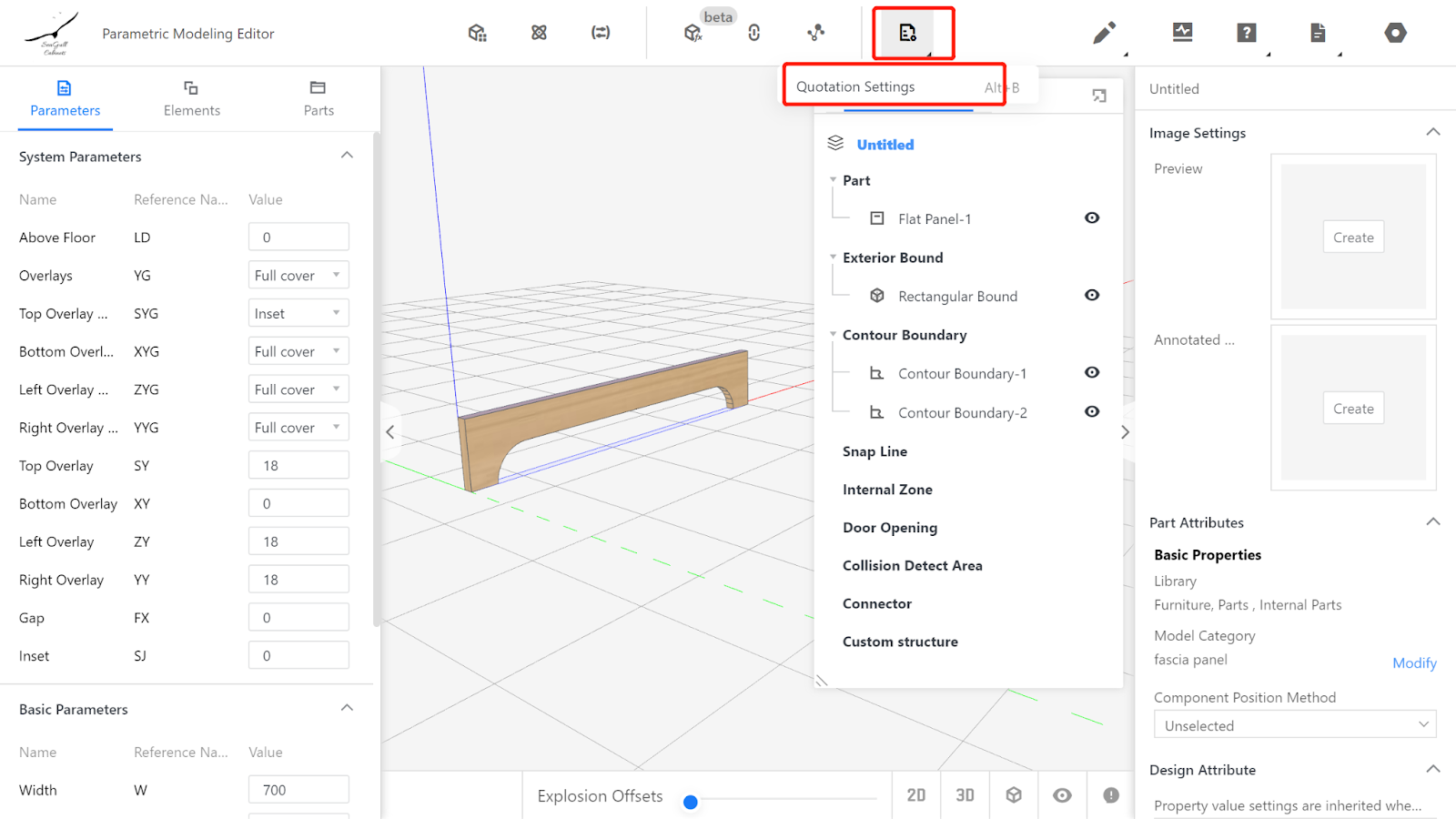
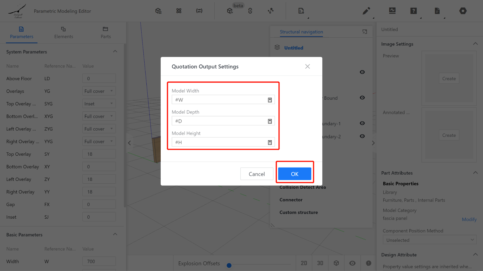
V. Setting Output Attributes
The dimensions displayed in the export list correspond to the texture direction of the Panel. Width corresponds to the size in the texture's direction (X-axis) displayed in the editor, so width is #W;
Depth corresponds to the size in the vertical texture direction (Z-axis) displayed in the editor, so depth is #H;
Height corresponds to the thickness direction of the Panel displayed in the editor (Y-axis), so height is D.
VI. Model Testing
Enter values within the optional or range limits of the input parameters and check if the model's changes align with the parameter changes. If they match, it indicates that the model is correct. To ensure accuracy, every parameter must be thoroughly tested. (In the given example, only the width W and arc radius R need to be tested, as depth D and height H have one optional value each and do not require testing.)
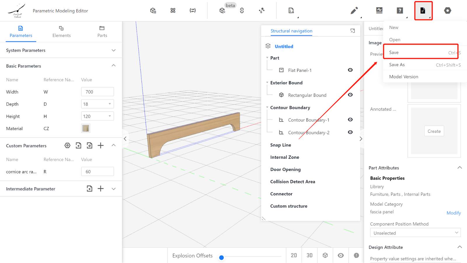
VII. Saving to the library
Click on the file in the upper-right corner, select Save, choose the subdirectory for saving, and click Save.
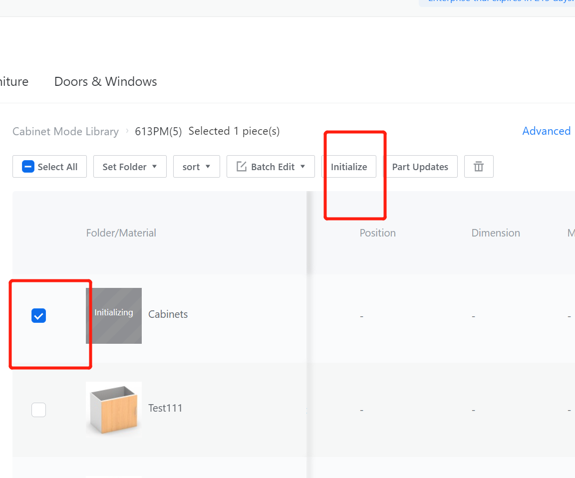
In the corresponding category on the Product page, find the model, select it, and click Store to wait for the model rendering to complete.