Definition: It is used to add special adaptation rules that are not preset by the system to special components. It is mainly used for corner boards and corner-cutting boards.
Create Location
Enterprise Catalog > Custom Products > Kitchen & Bath / Custom Furniture > Advanced > Parts Adapation Rules
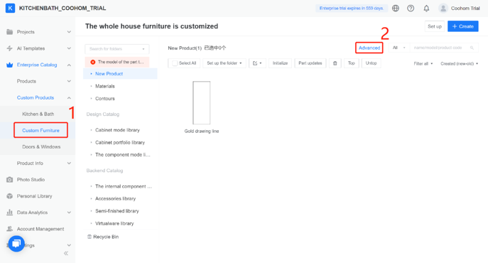

Introduction to Parts Adaptation Rules
1. Enter the name of the adaptation rule (e.g. corner cabinet shelf)
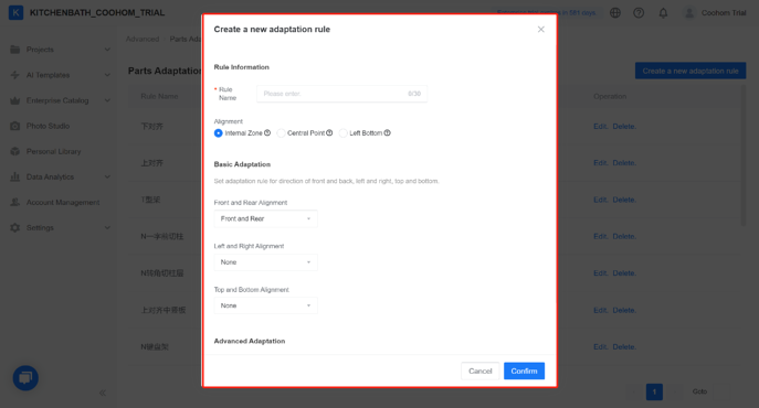
2. Choose an alignment mode.
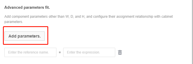
3. Add advanced parameter association. The user can define the adaptation requirements for other parameters except for #W, #D, #H during component adaptation.
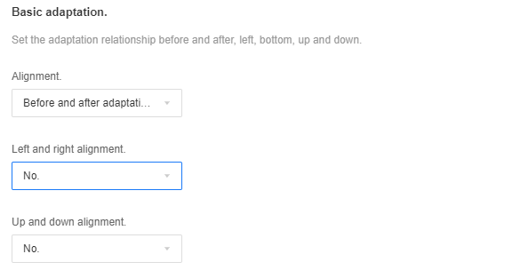
4. Alignment
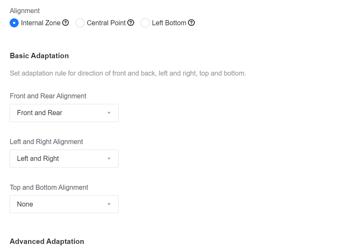
The first method (the most common): align with the inner space as the reference, which means that the alignment and adaptation will be performed according to the found inner space area during the adaptation process
When selecting a single direction, the offset and the main parameter input box of that direction will be activated
The second method: align with the cabinet body (center point) as the reference, which means that the cabinet body will be found according to the inner space during the adaptation process, and then according to the set component center point coordinates (X, Y, Z) and Align and offset the relationship of the center point coordinates of the cabinet (0,0,0)
The third method: align with the cabinet body (left rear bottom) as the reference, which means that during the adaptation process, the cabinet body will be found according to the inner space, and then according to the set component left and bottom coordinates (X, Y, Z ) Align and offset the relationship between the bottom left and bottom coordinates of the cabinet (0,0,0)
In the second or third method, you can enter the specific board coordinate values (x, y, z) in the front, back, left, and right directions to determine the precise positioning of the component when it is adapted to the inner space, and enter the specific main parameter expression (or value) to determine the specific size of the component
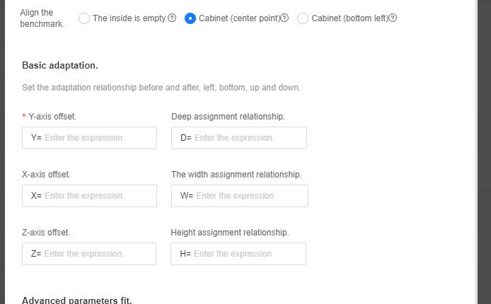
L-shaped shelf adapation rules
1.First enter the name of this adaptation rule, and then select the alignment reference as the inner void (generally select the inner void as the alignment reference for the corner laminate), and finally select the front and rear adaptation and left and right adaptation
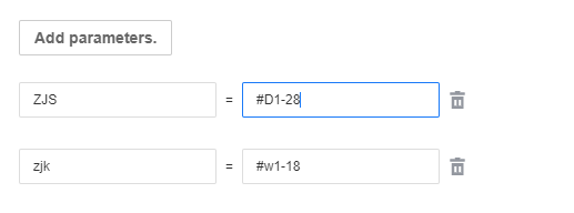
2. Correlate the advanced parameters corresponding to the shelf and the cabinet, the actual value is determined according to its own process
Note: the component parameters are written on the left side of the equation, and the cabinet parameters are written on the right side of the equation and the # sign is added in front;
The corner parameter size of the shelf needs to be read to fit the shelf to the correct size in the cabinet (that is, when the shelf is called into the cabinet for modeling, the corner size of the shelf needs to be related to the corner size calculation in the cabinet), where ZJS =#D1-28 in 28 represents the distance from the front end of the back panel to the rear of the cabinet (that is, the thickness of the back panel + the amount of forward movement of the back panel). This value varies according to the process of the cabinet
3. Find the L-shaped shelf and click View to enter the editing interface, click Edit Details; click Attribute Edit, select the adapted behavior and click Save
Adaptation rules for corner cut laminates
1. Open the component adaptation rule configuration page and create a new adaptation behavior
2. Enter the name of this adaptation rule first, and then select the alignment reference as the cabinet (bottom left, rear) (the alignment reference of the general corner-cutting laminates). Choose cabinet (center point) or cabinet (bottom left). Which one can be consistent with the model modeling reference point)
3. Front and rear position: Y=-the distance from the front of the back panel to the rear of the cabinet (that is, the thickness of the back panel + the amount of forward movement of the back panel), D=#D-the distance from the front of the back panel to the rear of the cabinet (that is, the back panel Thickness + forward movement of backplane);
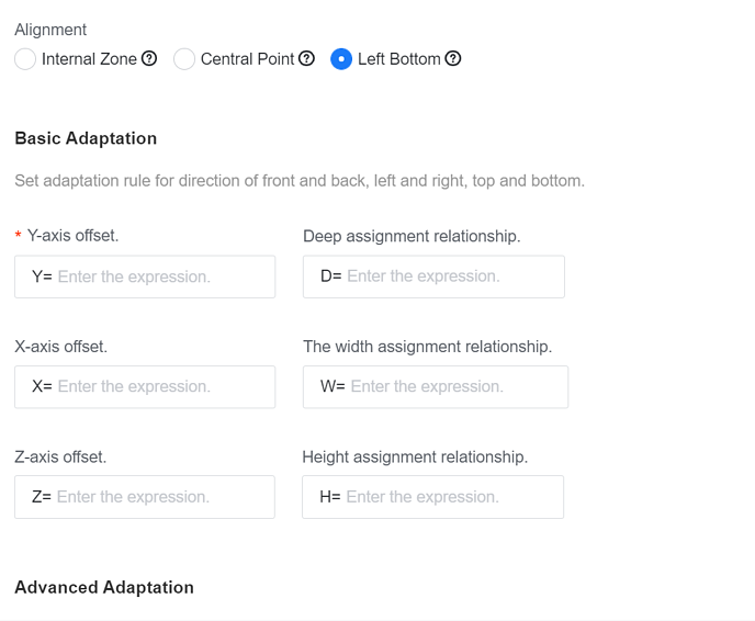
Left and right position: X = thickness of the left plate, W = #W-thickness of the left plate-thickness of the right plate
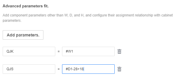
4. Associate the advanced parameters corresponding to the shelf and the cabinet, the actual value is determined according to its own process
Note that the component parameters are written on the left side of the equation, and the cabinet parameters are written on the right side of the equation and the # sign is added in front;
The cut corner parameter size of the shelf needs to be read to fit the shelf to the correct size in the cabinet (that is, the cut corner size of the shelf needs to be related to the corner cut size calculation in the cabinet as if the shelf is called into the cabinet for modeling) , Where 28 in QJS=#D1-28+18 represents the distance from the front end of the back panel to the rear of the cabinet (that is, the thickness of the back panel + the amount of forward movement of the back panel). This value varies according to the process of the cabinet
5. Find the corner-cutting layer and click View to enter the editing interface, click Edit Details; click Attribute Edit, select the adapted behavior and click Save.