Background
To align with the technical standards for integration, the execution should be based on the component integration technical standards. The following content is a partial selection of text with differences, such as category codes or the integration of new products. This document should also be synchronized with the logic of integrating new products in subsequent Bill of Materials (BOM) disassembly.
Disassembly Applet Docking
1. Product Docking
1.1 BOM Disassembly Applet
● As a member of the All-Line Assistant mini-program, the Splitting Assistant is mainly responsible for the splitting module capability. In terms of product integration, the model itself does not need to be integrated and restored like PC software. It only needs to handle model splitting, hardware display, and production data output. The modeling process is also subject to integration technology standards. We need to model the model according to the standards. In the integration with the Splitting Assistant, most of our product integration methods and component integration technology standards are consistent, with only a few differences. Below, we will describe the specific integration methods for several major types of products.
1.2 Modeling Docking
● During the docking process, we also need to use the Coohom Parametric Editor to modify the model products and output certain standard information that aligns with different manufacturers in the industry. This includes details such as drilling holes, edge banding, textures, and notes on the panels. Personnel are required to use the editor to complete these modifications. Afterwards, the models and information are combined using design tools to generate solution data. This data is then passed on to the Bill of Materials (BOM) for disassembly, where the information is splited and written into the BOM. The BOM interacts with other programs to further process the data.
1.3 Industry Code
● As part of the applet, specific identity codes have been created for various product categories in the custom industry. The applet will use these unique codes to process and output different product data. The industry category codes are filled in the custom code section at the product commodity level. The specific content to be filled in will be explained in each product description below.
1.4 BOM Industry Category List
2. Panel Catalog
2.1 Basic Panel
① Modeling Method
According to the logic of panel docking, the following content is used to standardize the modeling methods for rectangular panels, irregular-shaped panels, slotted panels, holed panels, and other panels. Specific modeling steps:
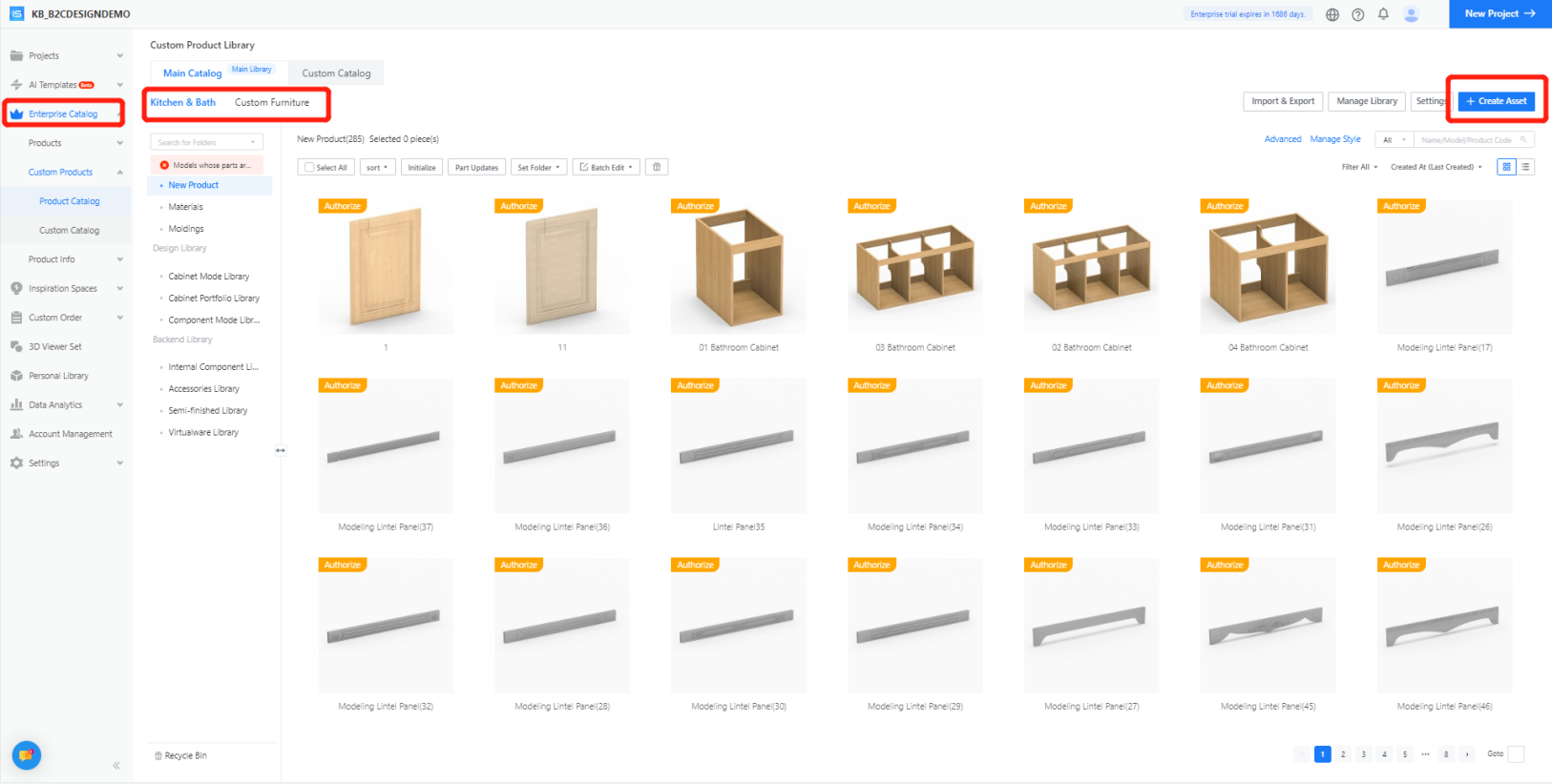
Step 1: Select [Enterprise Catalog]- [Custom Furniture / Kitchen & Bath] - [Create Asset]
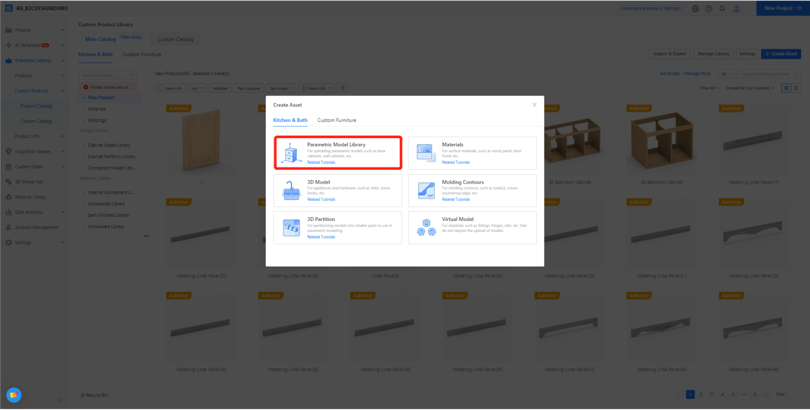
Step 2: In the pop-up interface, select [Kitchen & Bath] - [Parametric Model]
Step 3: [Interim (WIP) Parts] - [Cupboard Panel] - [OK]
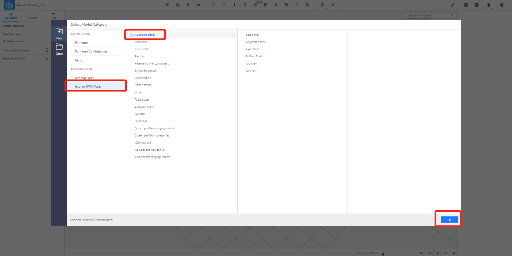
Note:The docking of panels is not limited to ordinary panel categories, but also supports other panel categories, such as movable door cores and concealed door cores, as long as they are confirmed to be the docking layer.
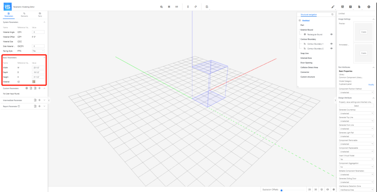
Step 4: Setting [Basic Parameters]
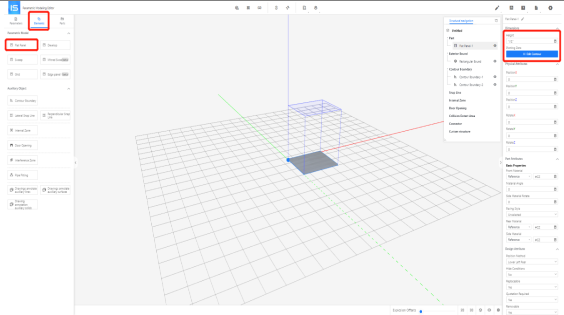
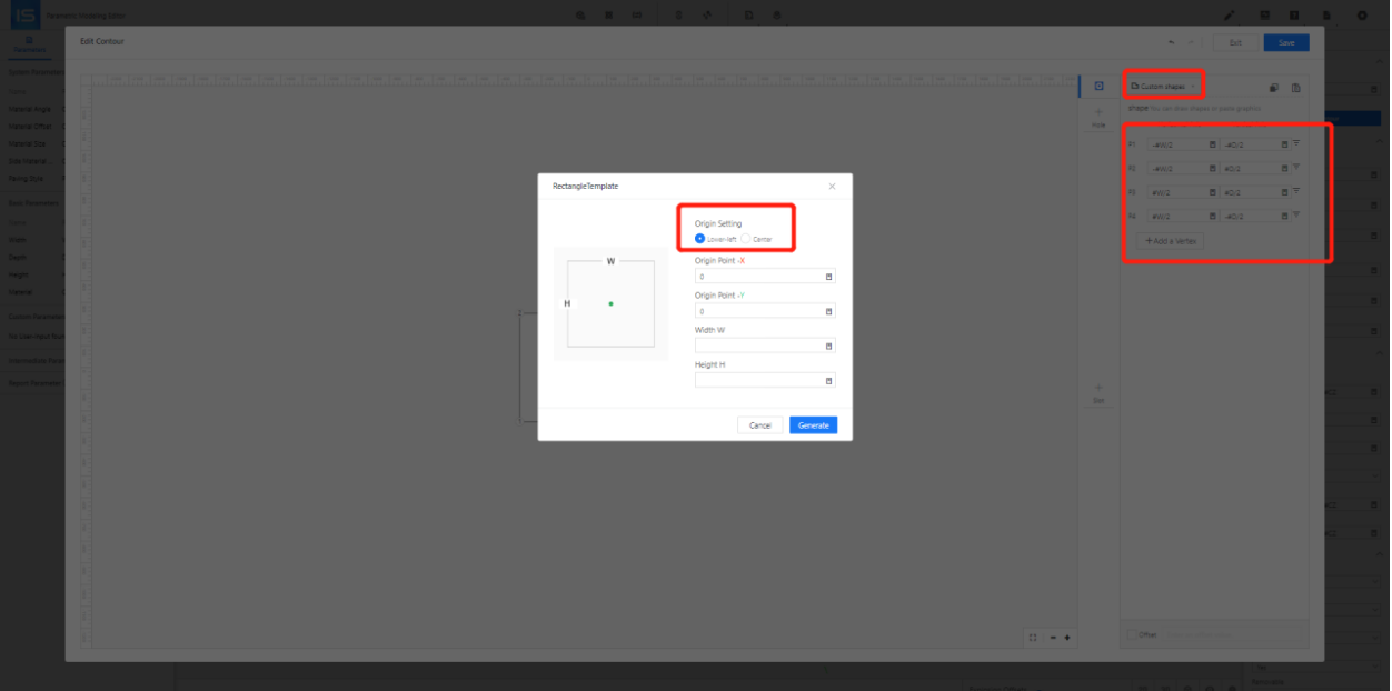
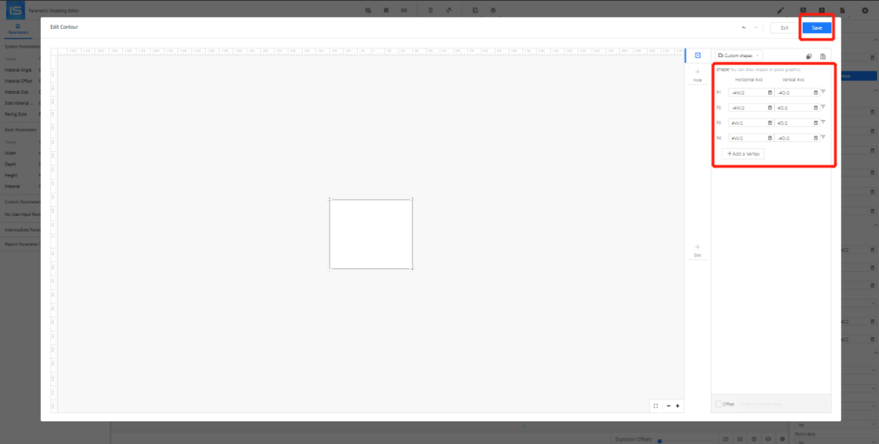
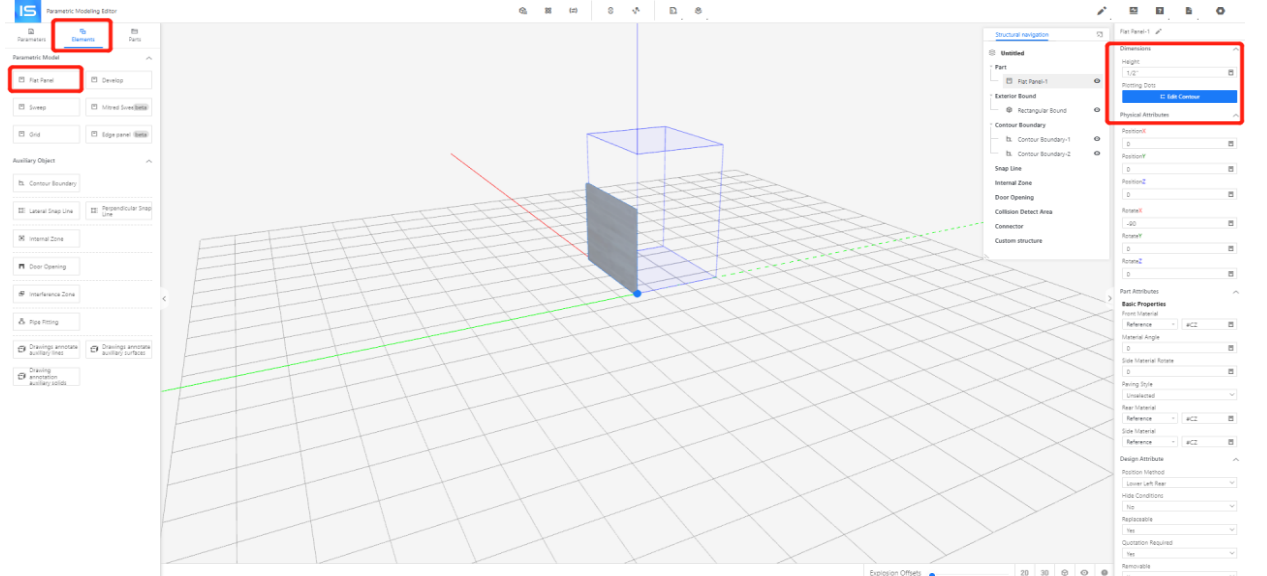
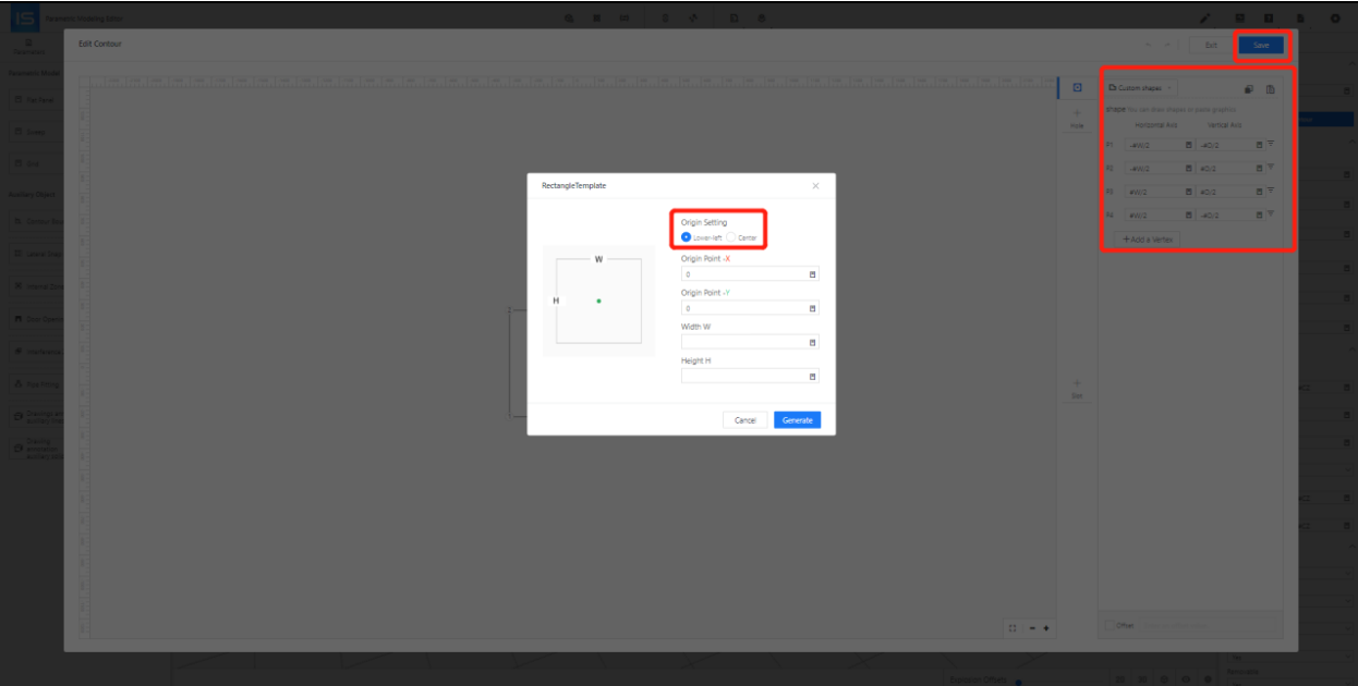
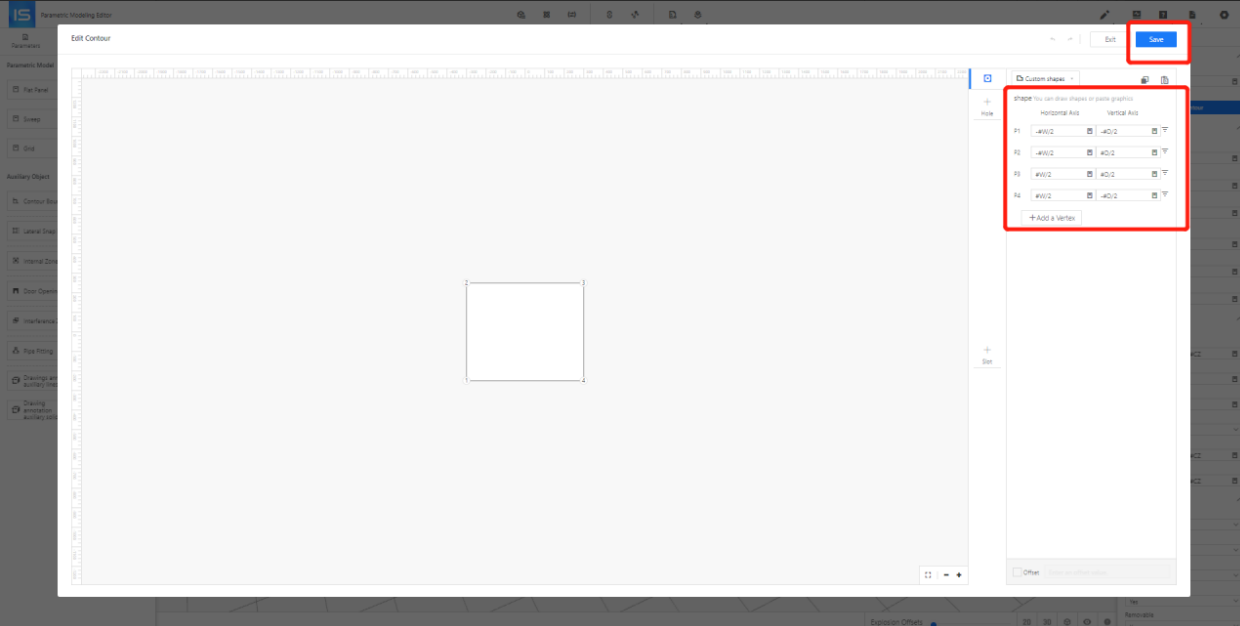
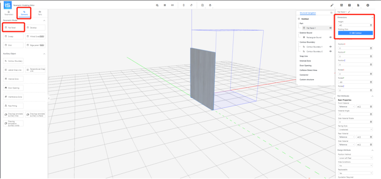
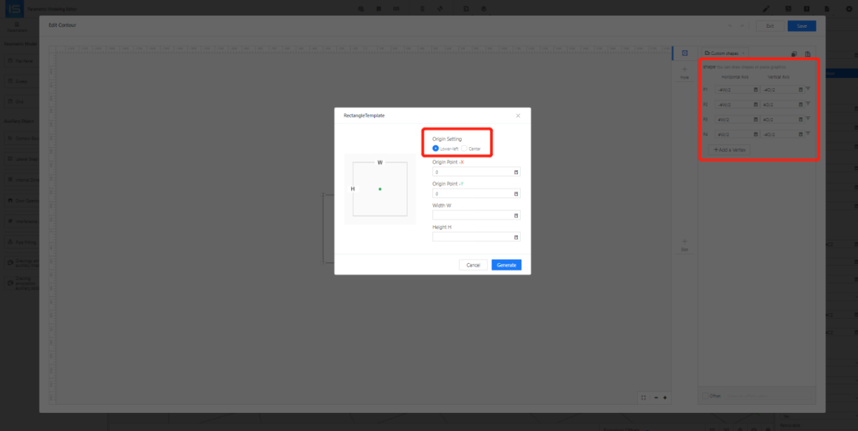
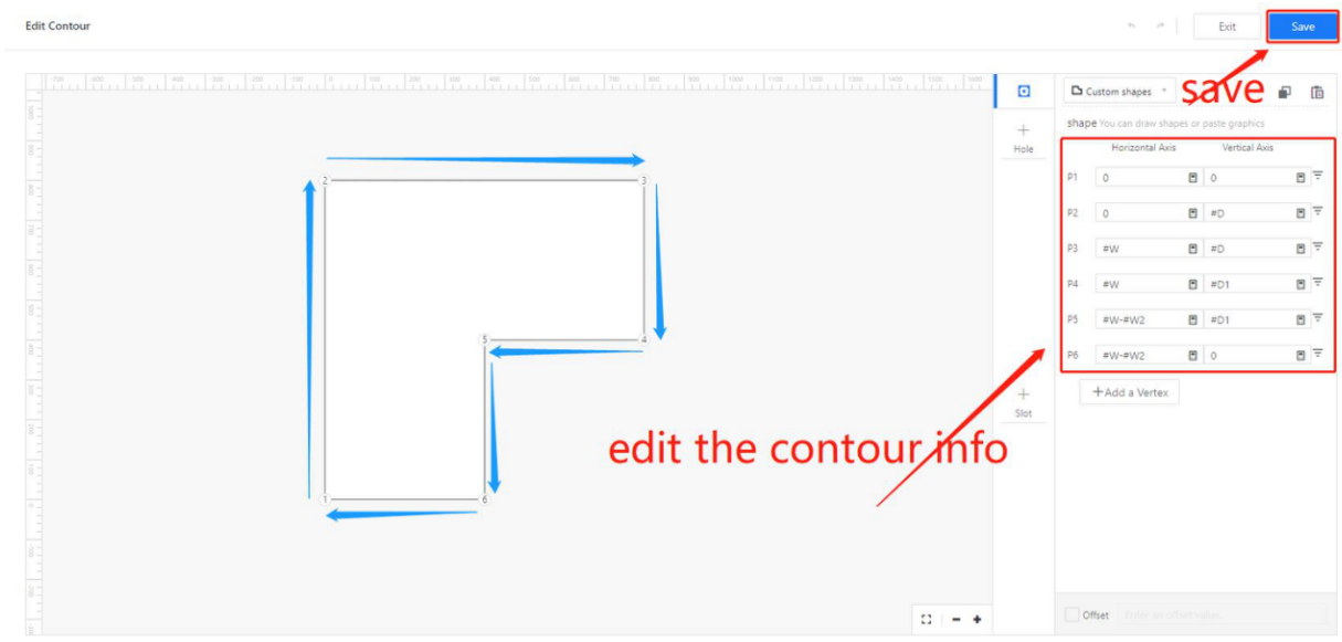
Step 5: Select [Elements] - [Flat Panels] - [Height ] to associate parameters with the thickness direction of the panel - [Edit Contour] - In the pop-up interface, perform [Point Editing] - [Save].
Step 5: Select [Elements] - [Flat Panels] - [Height ] to associate parameters with the thickness direction of the panel - [Edit Contour] - In the pop-up interface, perform [Point Editing] - [Save].
Tables can't be imported directly. Please insert an image of your table which can be found here.
Horizontal panel
Vertical Panel
Back Panel
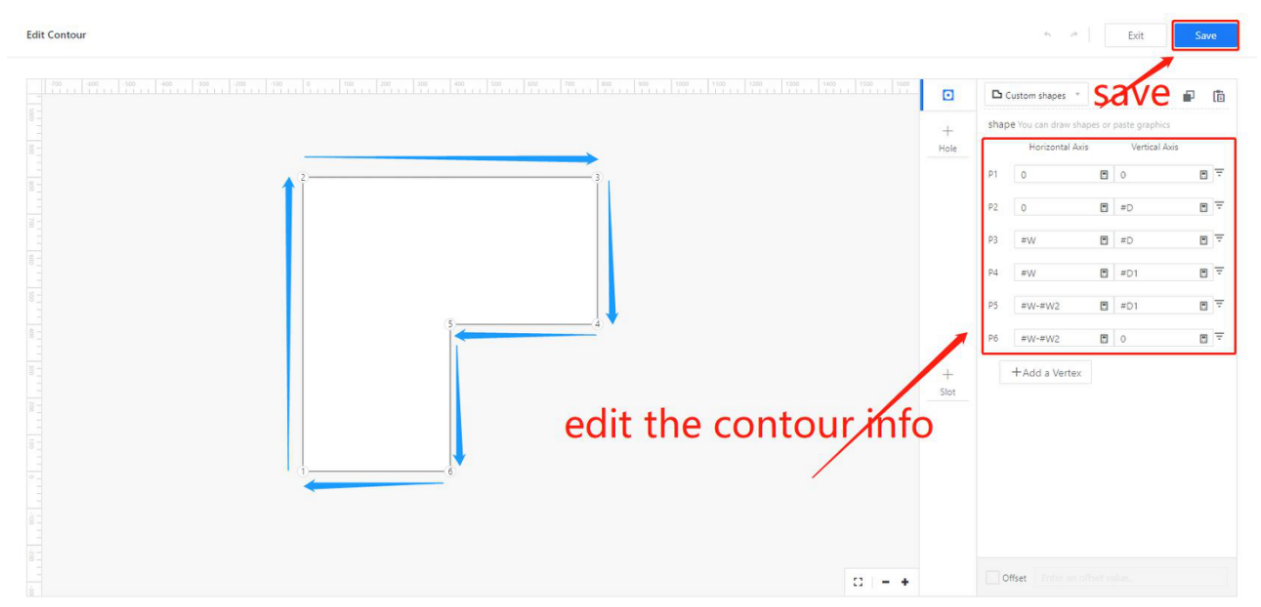
Other panel outline examples
Tables can't be imported directly. Please insert an image of your table which can be found here.
Supports irregular shapes
Corner cabinet horizontal panel
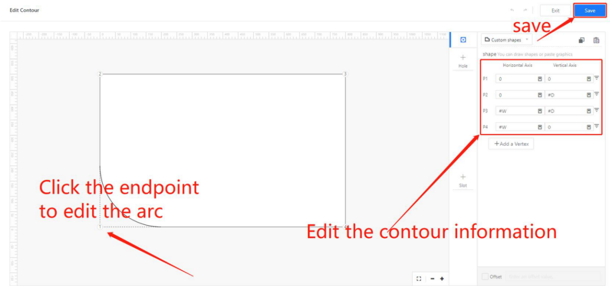
Arc slab
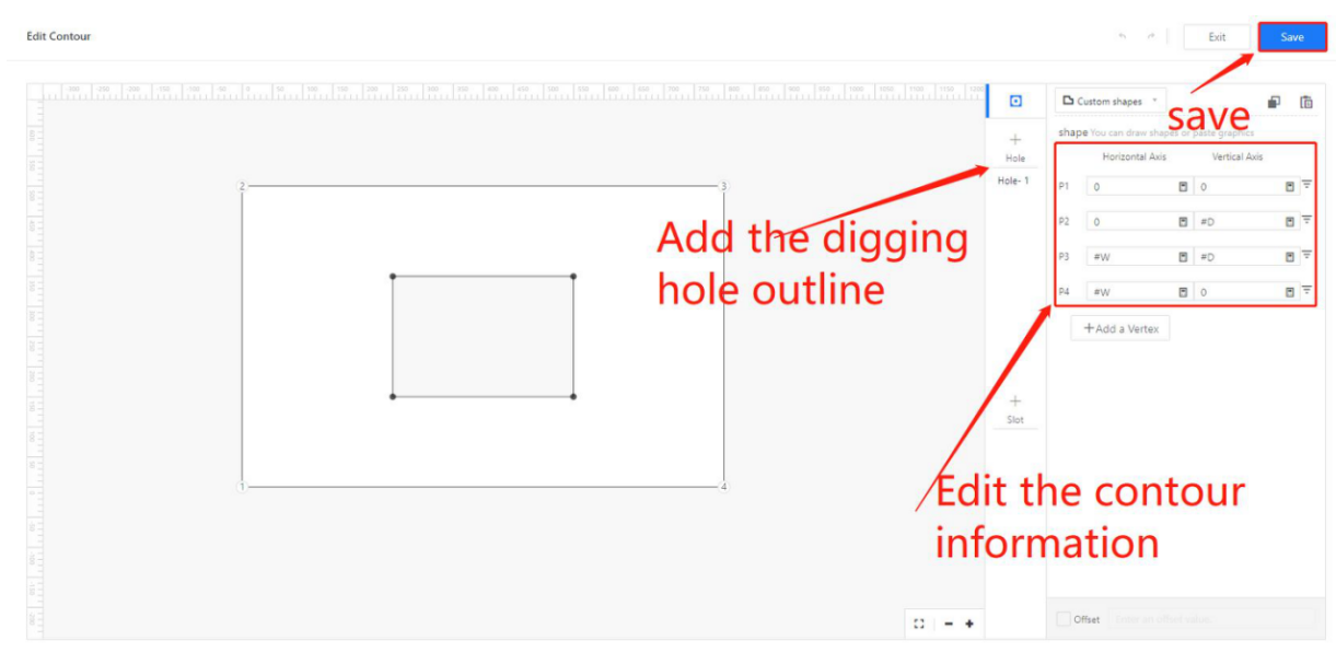
Internal hole panel
Beveled Panel
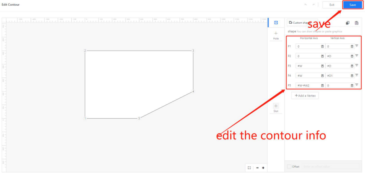
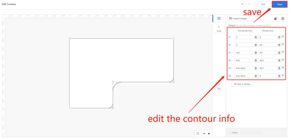
L-shaped desktop panel
Wine Panel
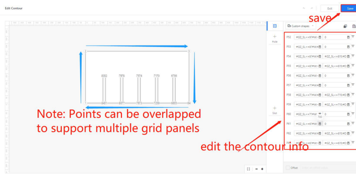
● Support overlap between contour points
Key Point:
- Panel docking is only applicable to flat panel components.
- The subcomponents of the panel docking layer are limited to a single flat panel component. However, other types of components are allowed on the same layer, such as patterned components or swept components.
- The outline of the panel is defined by specifying the points in a clockwise direction, starting from the bottom left corner. All points should be located in the first quadrant.
- Panel docking supports internal cutouts or holes within the panel.
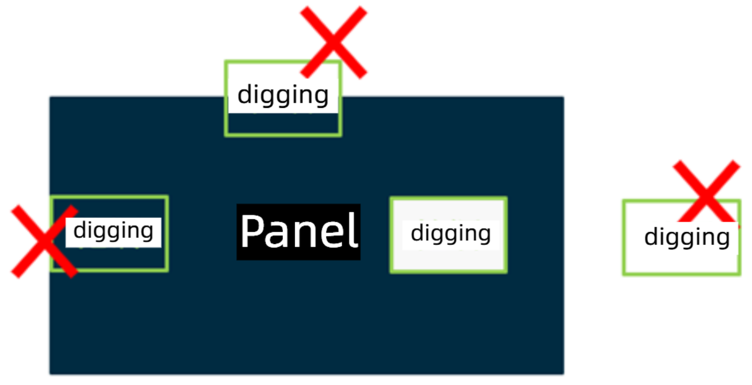
● Panel outlines and cutouts do not support elliptical shapes for production docking.
● Overlapping of points in the panel outline is supported.
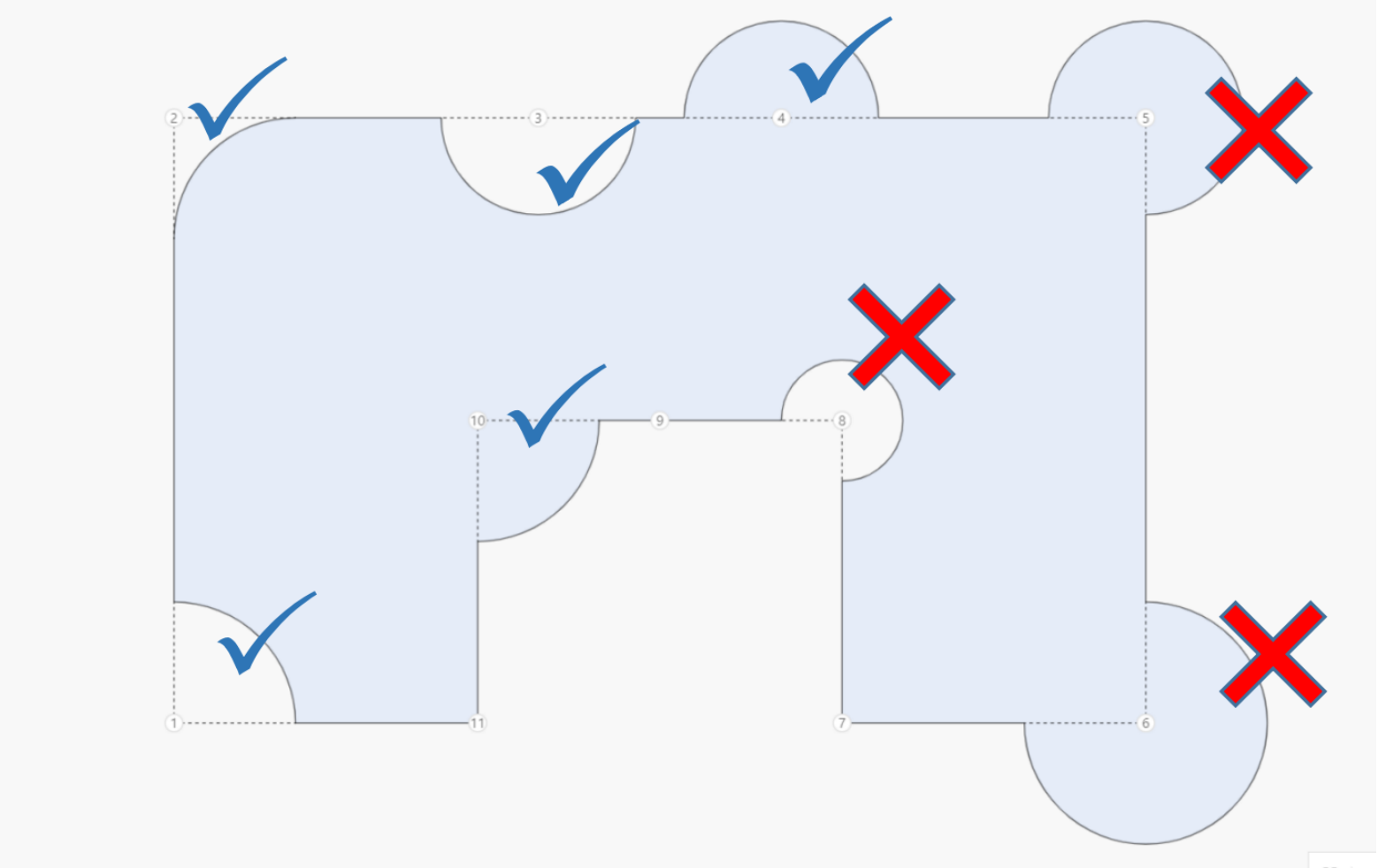
● Both panel outlines and cutouts only support concave arcs, not convex arcs.
- Convex Arcs: Arcs with a central angle greater than 180°.
- Concave Arcs: Arcs with a central angle less than or equal to 180°.
In the actual modeling process, there are two ways to create circular arcs: point-based and edge-based.
a. Point-based Arc
b. Edge-based Arc
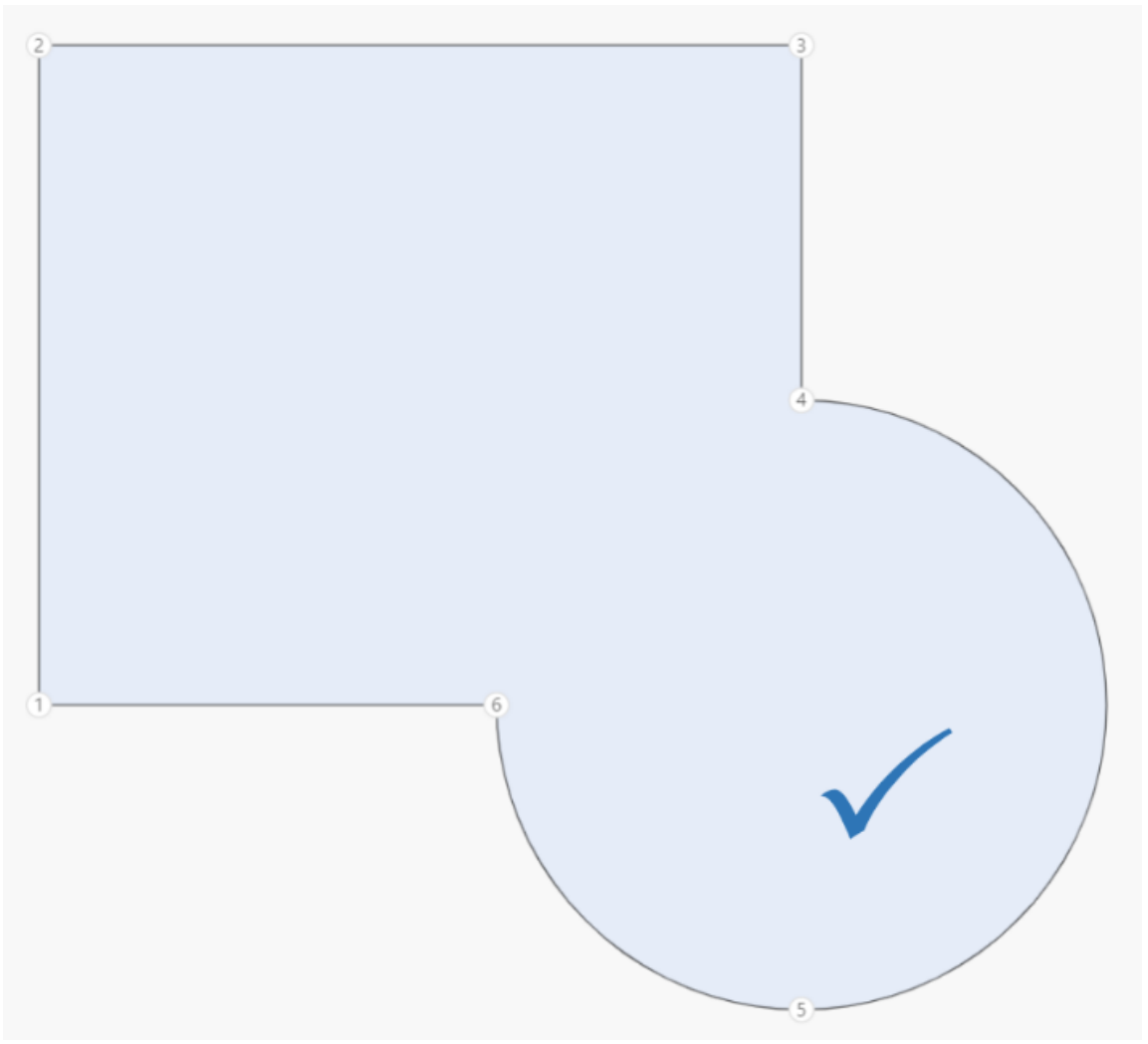
Fillt Arc Solution
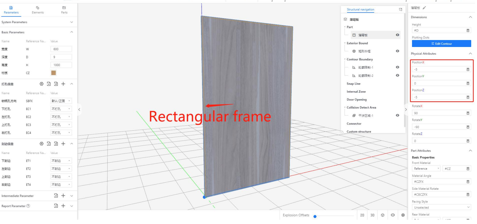
The customer indeed needs to create a fillet. It is possible to add additional anchor points on the contour to split the fillet into multiple smaller arcs. For example, in the diagram below, by adding a fifth point, the original 270° arc can be divided into two arcs, one of 90° and another of 180°, achieving the desired fillet effect.
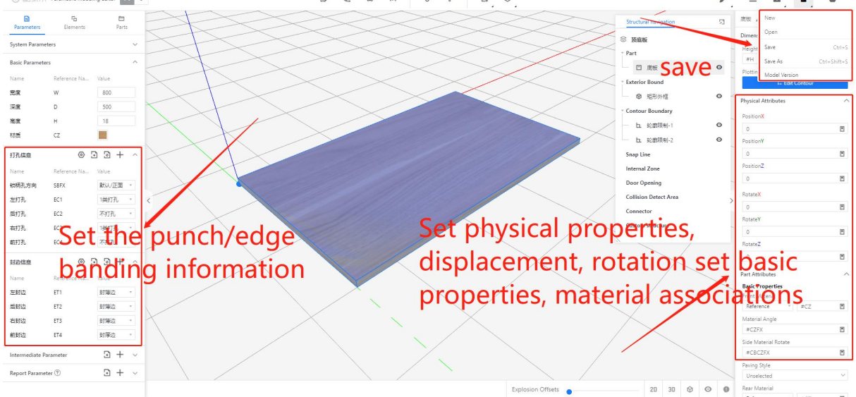
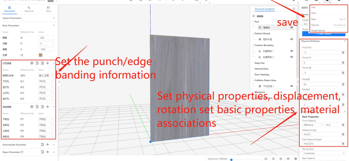
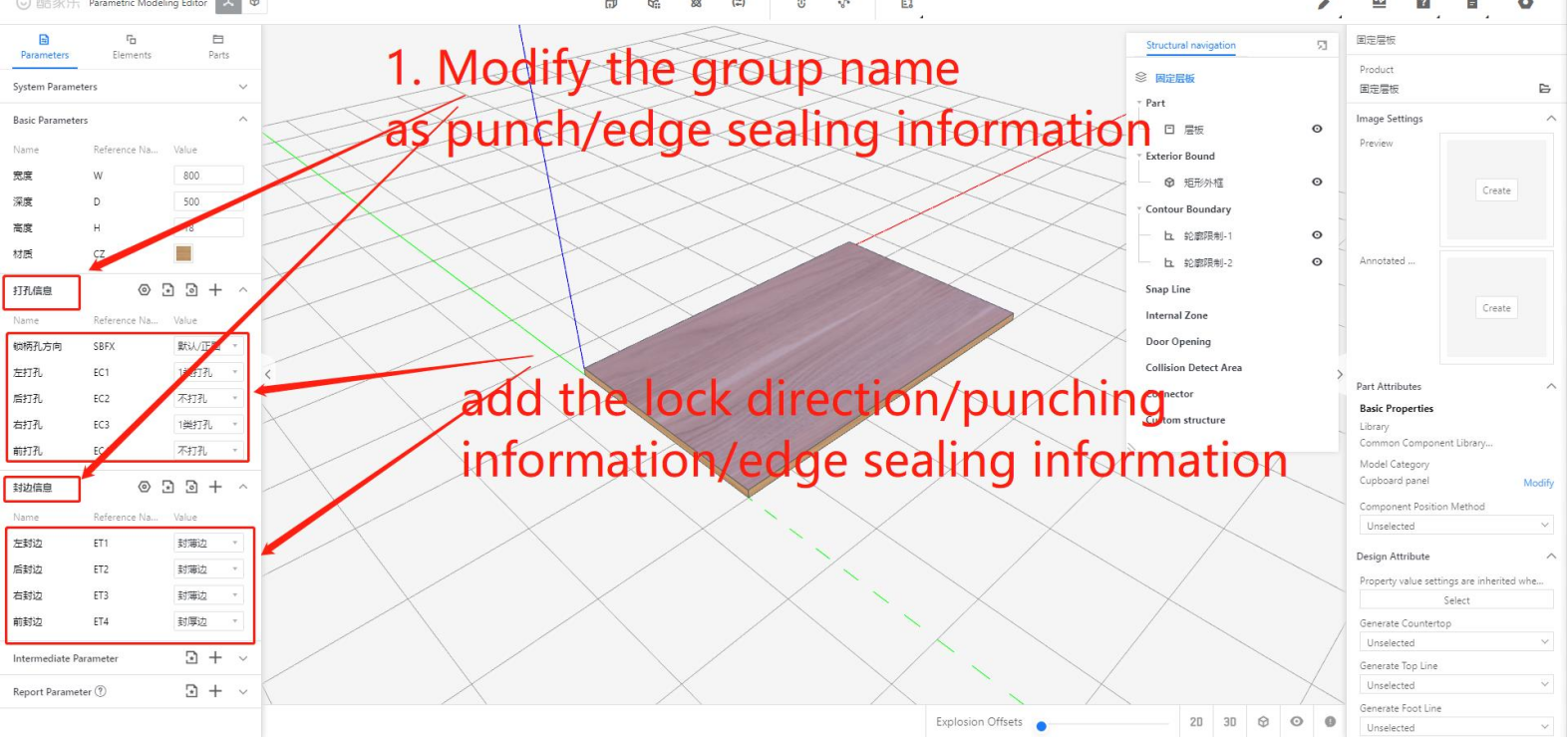
Step 6: In the saved interface, set the component's physical properties such as coordinates and rotation. Associate the [Material Angle] with #CZFX and the [Side Material Angle] with #CBCZFX. Add the [Hole/Edge Parameter.] Finally, click on the save icon in the top right corner or use the shortcut CTRL+S to save the changes.
Tables can't be imported directly. Please insert an image of your table which can be found here.
Horizontal panel
Vertical panel
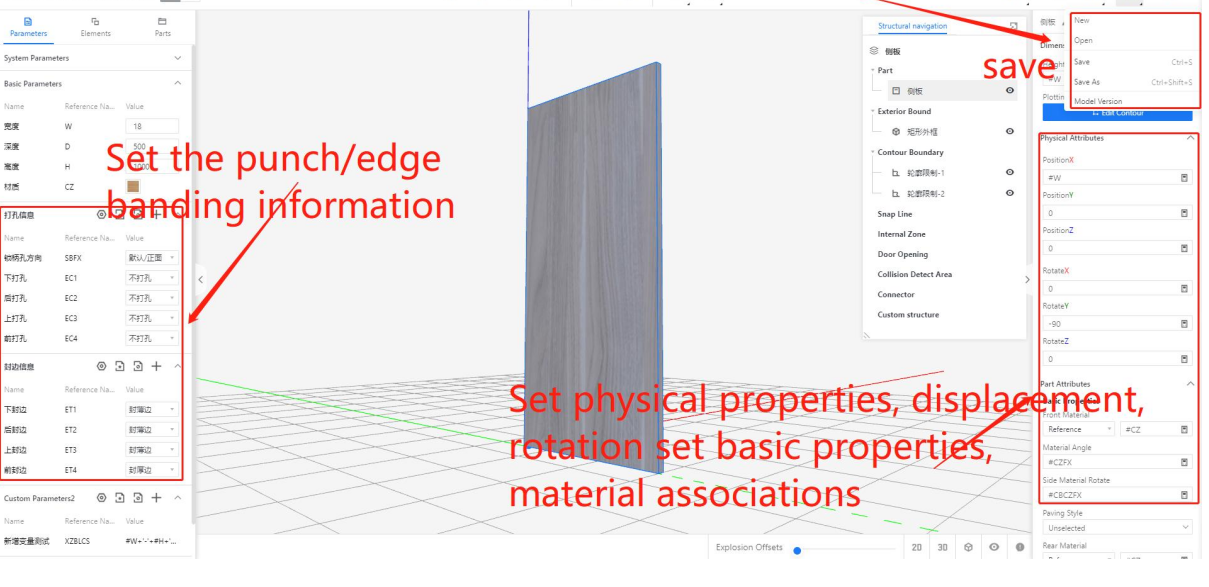
Back Panel
The logic for hole punching and edge banding
● Logic
In the storage state of the component, determine the hole edges among the six faces.
Tables can't be imported directly. Please insert an image of your table which can be found here.
Name
Figure
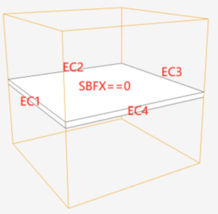
Horizontal panel
When the upper and lower sides of the model are the front and back sides of the plate, determine the hole edge according to the following figure
Vertical panel
When the left and right sides of the model are the front and back sides of the plate, determine the drilling edge according to the following figure.
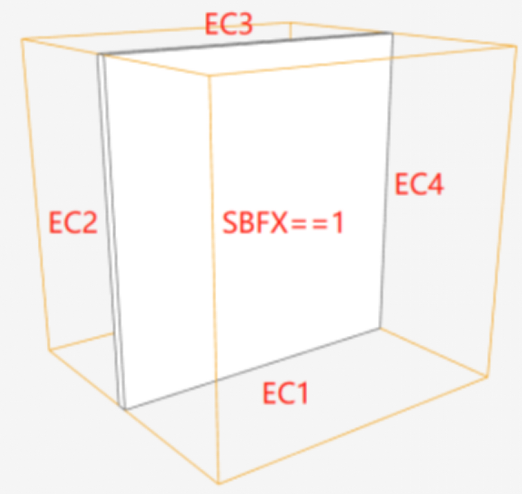
Back Panel
When the front and back faces of the model are the positive and negative sides of the board, the hole punching edge can be determined based on the following diagram.
Note: The shaped panel is the same as the rectangular panel, only four directions of the edge punching parameters.
● Logic
Equivalent to punch edge logic
● Parametric Setting
Tables can't be imported directly. Please insert an image of your table which can be found here.
Type
Parametric
Parametric Type
Display Name
Value
Information
Punching mode
#EC1
#EC2
#EC3
#EC4
integer
No punching
0
Representing that the current punching edge does not produce holes
Type 1 punching
1
The default cabinet connection method can represent three-in-one connections, invisible cabinet connectors, etc. The ecological configuration takes precedence.
Type 2 punching
2
Used for fixing movable shelves, it can represent two-in-one connections, three-row holes, etc. The ecological configuration takes precedence
Type 3 punching
3
Used for fixing hinge plates, representing hinge holes
Type 4 punching
4
Used for fixing slide rail plates, representing slide rail guide holes
Type 5 punching
5
Customized punching method used for the library construction party to define hole punching methods that are suitable for the library, such as three-row holes, crescent pieces, double-ended connecting rods, hammer head nuts, etc
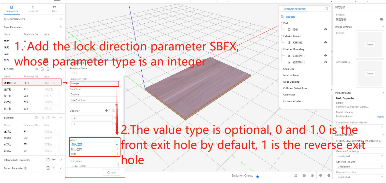
#SBFX
integer
No punching
6
Customized hole punching method
#SBFX
integer
......
......
......
No punching
0
No punching
Thin edge banding
1
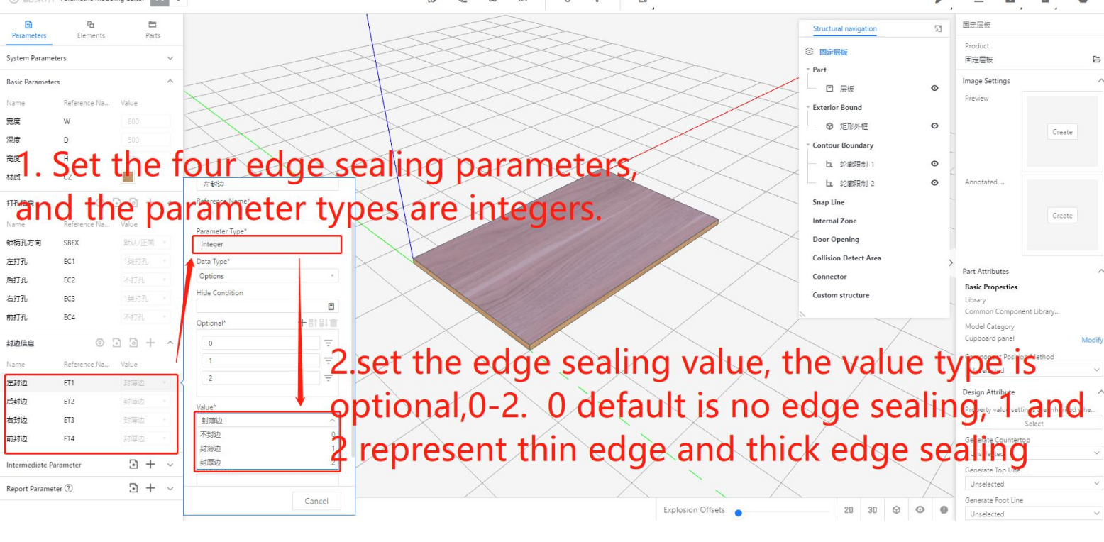
"Thin edge banding" and "thick edge banding" actually represent the thickness of the edge banding. For example, thin edge banding has a thickness of 0.5 millimeters, while thick edge banding has a thickness of 1.2 millimeters. These values can be configured and adjusted using the Ecological Direction software.
Edge banding method
#ET1
#ET2
#ET3
#ET4
integer
Thick edge banding
2
"Thin edge banding" and "thick edge banding" actually represent the thickness of the edge banding. For example, thin edge banding has a thickness of 0.5 millimeters, while thick edge banding has a thickness of 1.2 millimeters. These values can be configured and adjusted using the Ecological Direction software.
Customized edge banding
3
The edge banding thickness for components other than the regular cabinet body, such as door panels, is 2.0 millimeters.
......
......
......
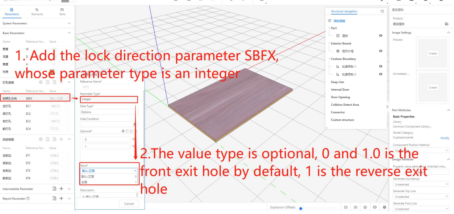
Specific parameter setting example:
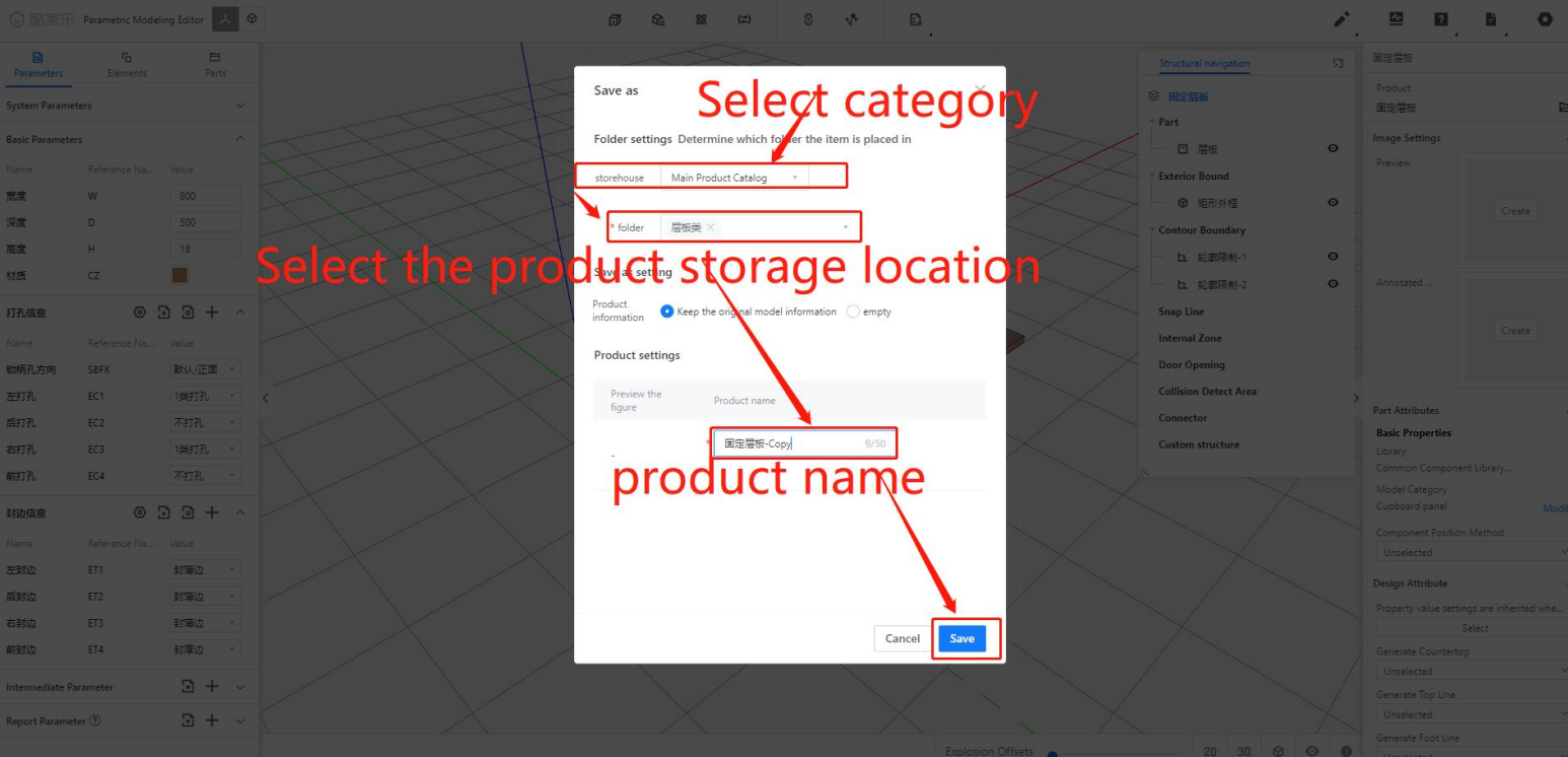
Step 7: In the interface after saving - [Select Category] - [Select Storage Location] - Enter [Product Name] - Click [Save]
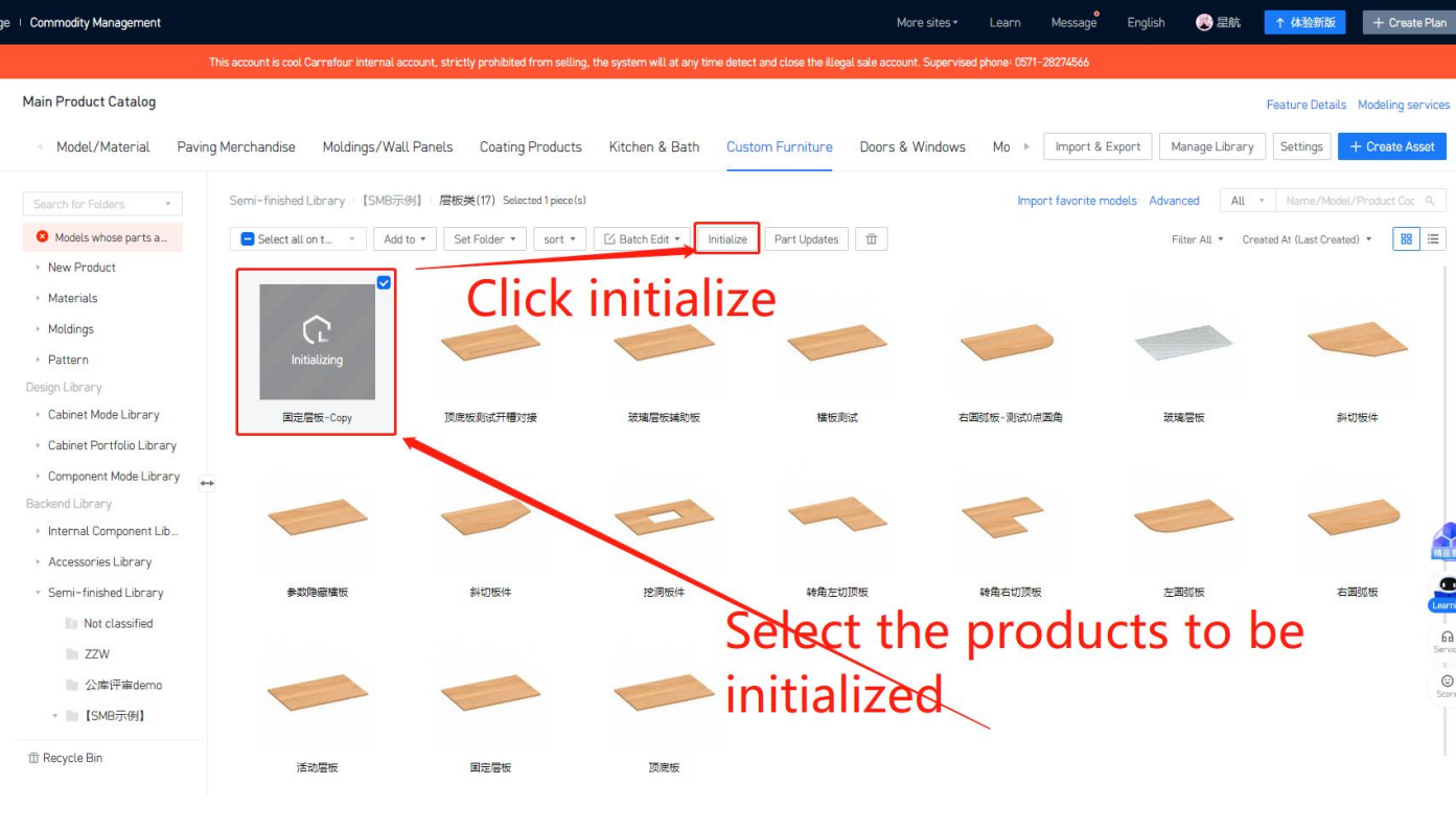
Step 8: Switch to the back-end of the product - [Custom furniture] / [Kitchen & Bath] - Check the pending entry [Product] - Select [Inbound], representing the completion of parameterized modeling for the board components.
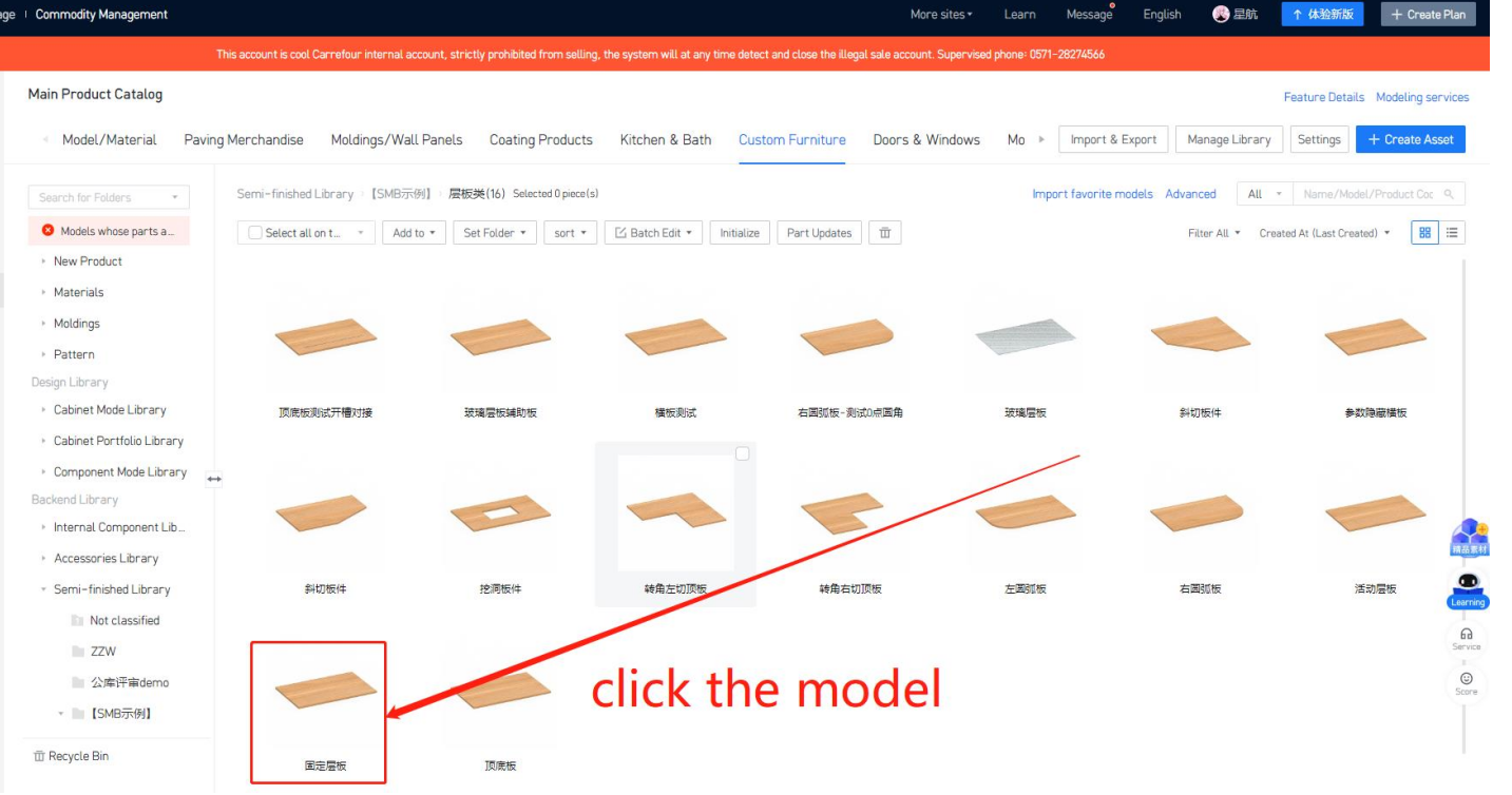
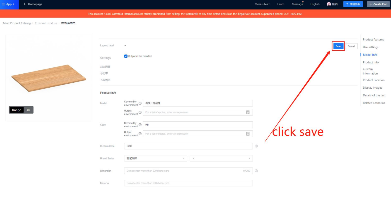
Step 9: How to add a model code: After clicking on the model in the inventory, on the new page, click [Edit] - Enter [Model]/[Product Code] - After completing, click [Save].
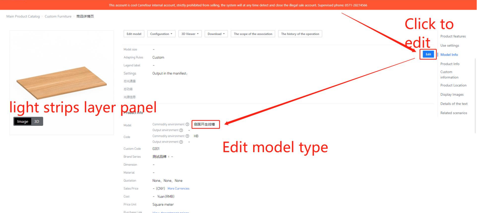
Note:In this case, the model code can be outputted to the remarks section in the inventory list for the LED strip layer board with slot.
Step 10: When the panel component is used by an intermediate layer or cabinet
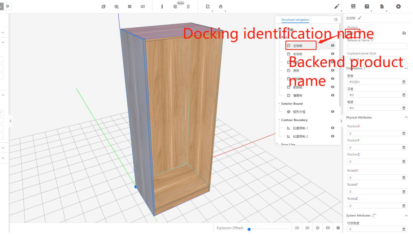
● The applet itself is integrated using custom codes. The backend product name may not necessarily match the parameterized editor's structure navigation bar name. The output name should be based on the structure navigation bar name.
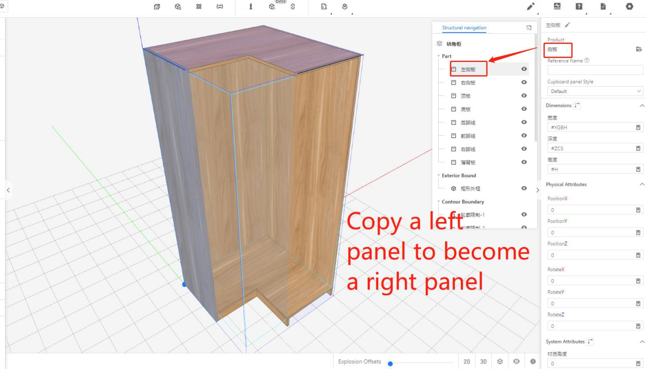
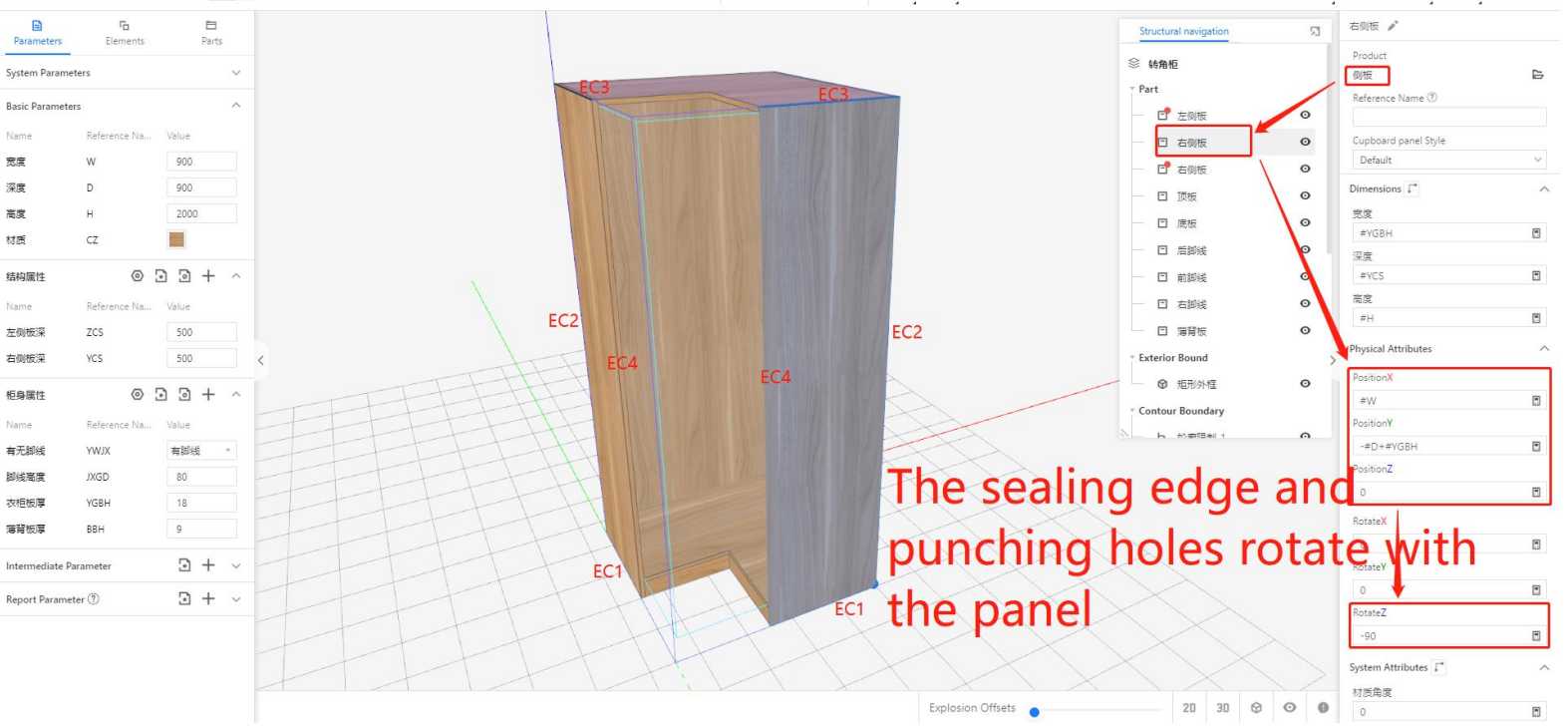
l When the panel component is called by a cabinet or middel layer, it supports rotation. The edge banding and hole punching should follow the rotation accordingly.
In the case of a corner cabinet, the left and right side panels may have different orientations.
-
Selecting "Yes" for the component attribute inheritance of the current board component ensures that parameters like hole punching and edge banding stay in their current state, regardless of any updates to the panel component. This means that the parameter configuration will be inherited regardless of whether the panel component is updated or not.
Selecting "Yes" for the component attribute inheritance of the current board component ensures that parameters like hole punching and edge banding stay in their current state, regardless of any updates to the panel component. This means that the parameter configuration will be inherited regardless of whether the panel component is updated or not.
Note:If the component attribute inheritance is not selected as "Yes," individual parameters can still be associated with cabinet parameters or set to a formula state (as shown in the diagram). In this case, the parameter will be inherited by default.
② Industry Catalog
● Conventional production type panel components
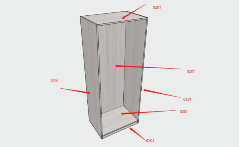
In applet, for panel-type products, it is necessary to fill in the corresponding custom code: 0201.
Note that if this field is left blank, the board component will not be included in the calculation and splitting process. Additionally, the slots will not be generated for the board component in applet, and the board component information will not appear in the material list. By filling in the custom code as 0201 for the panel component, the slot calculations will include the incremental values.
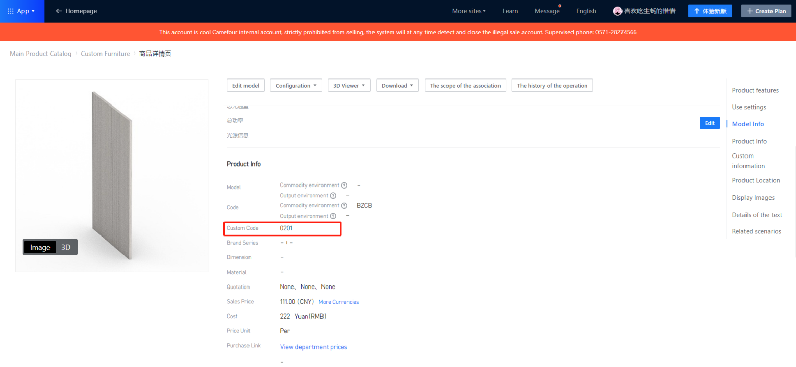
● Auxiliary panels that are not of production type include hinge panel, slotting auxiliary panel, etc.
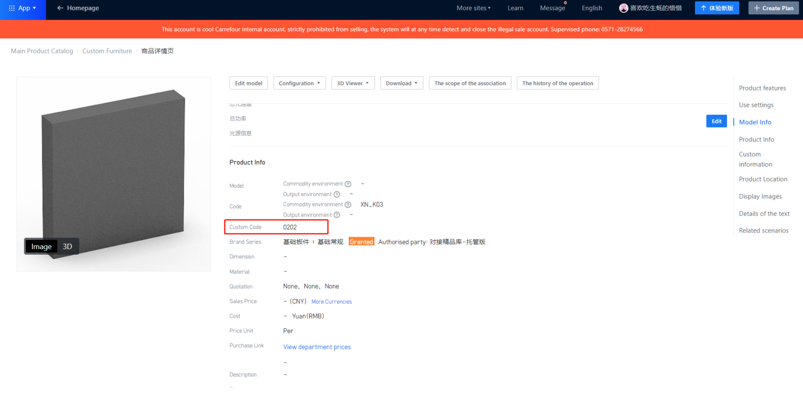
In the entire production process, for example, auxiliary components such as groove opening boards and hinge boards are only used for slotting or hole punching, but they do not actually participate in production. For these components, you need to fill in the corresponding code: 0202 in the custom code field at the commodity level.
Note: If you do not fill in the code, the final component will not be included in the order splitting calculation. Additionally, in the mobile application, no slots will be generated for the component, and the component information will not appear in the material list. When filling in the custom code for the component type 0202, the slot increment will not be calculated during the slotting process.
3. Door Panel Docking
3.1 Docking Standard
Same as the cabinet, the door panel needs to undergo PVC edge banding or other edge banding in order to complete the finished processing. It can participate in the layout optimization along with the cabinet panels. The joining method of edged doors refers to the joining of panels, so edge parameters need to be added in the door panel joining layer. Below are examples of parameter settings for these types of edge-banded doors.
① Flat Door Panel Docking
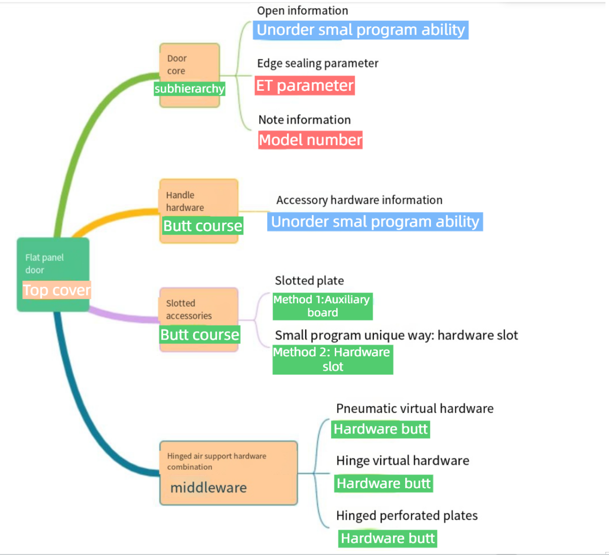
The joining of flat door panels mainly involves four components: door panel design, door core, handle, and hardware such as hinges and gas struts. Below is the hierarchical structure of the door panel:
② Industry Catalog
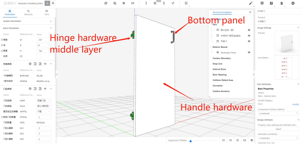
According to the above description, for the top layer of the flat door, we need to fill in the custom code as: 0309. In the editor, we need to call a bottom layer panel with a custom code: 0301.
Note: For modeling the bottom layer panel, you can refer to the reference panel.
3.2 Non-edge-banding Doors Standard
For door panels other than edge banding doors, such as those without edge banding, there is no need to perform edge reduction cutting, and thus no edge parameters need to be set. These door panels may have a door core or be composed of upper, lower, left, and right frames. If customers require data for joining these components, these subcomponents should be treated as separate items within the model library.
① Non-edge-banding Doors Docking
The non-edging door panel joint mainly consists of three parts: door panel shape, handle, and hardware such as hinges and gas struts. Below is the hierarchical structure of the door panel.
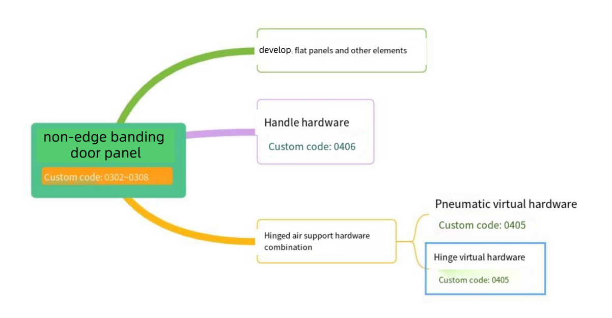
② Industry Catalog
● Non-edging door: Currently defined in applet, the types are roughly classified as:
Tables can't be imported directly. Please insert an image of your table which can be found here.
Panel Type
Industry Catalog
Blister door
0302
paint door
0304
solid door
0305
aluminium frame door
0306
Slat door
0307
Clad Door
0308
Electrostatic powder coated door
0310
3.3 The logic for perforating production-type door panels and others
● Scenario:
In our design process, there are cases where some door panels completely cover the neutral panel/top and bottom panels, etc. However, in the actual manufacturing process, only hardware holes such as hinge holes, handle holes, and straightener slots will typically appear on the door panels. There are no holes generated on the door opening or cabinet panels; only dummy doors or panel products will have holes drilled in them. Therefore, the handling method for the mini-program is as follows:
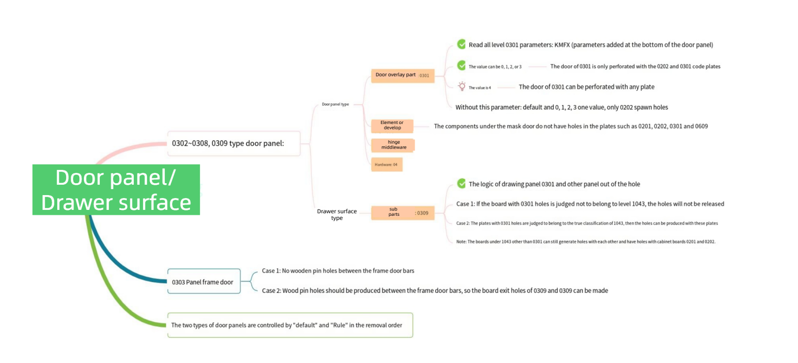
● Solution:
In the modeling process, when integrating flat panel doors with the mini-program, the custom code for the top layer of the clad door is fixed as 0309. Therefore, to implement this capability, we need to find the sub-component 0301 within the 0309 hierarchy. In the 0301 component, we will add a parameter called KMFX, which will have the same value as the KMFX in the clad door hierarchy. Additionally, we will associate the KMFX value from the clad door hierarchy to the sub-component hierarchy, passing the value along.
When applet processes the order, it will read this KMFX value and handle the relationship with the panel accordingly. The specific relationship handling is as follows:
Tables can't be imported directly. Please insert an image of your table which can be found here.
Panel Relation
Customize all boards whose code is 0301
KMFX == 0
0301 panel will not have holes with the 0201 cabinet panel, only with the 0202 auxiliary panel
KMFX == 1
KMFX == 2
KMFX == 3
KMFX == 4
0301 panels and all 0201,0202 panels have holes
No KMFX parameter handling at the bottom
0301 panel component does not require holes to be drilled in the 0201 cabinet panel. Instead, it requires holes to be drilled in the 0202 auxiliary board.
● Conclusion:
1. Therefore, the conclusion is that when the door panel is a hinged or false door, it needs to be adjusted according to the above method. If it is a door panel with edge banding and requires holes to be drilled in other components, then the underlying parameter should be set to "4".
2. At any time, the "0301" board component can be drilled with the "0202" type board component.
3. The door panel must always comply with logical rules such as interference slotting with other components and hardware slotting.
4. In the order assistant tool, a control button has been added to the configuration: "Default" and "Rules". The default option follows the previous processing logic, where if there is a collision and connection, a hole will be drilled. The "Rules" option refers to the current content on this page.
4. Hardware
4.1 Connecting Hardware
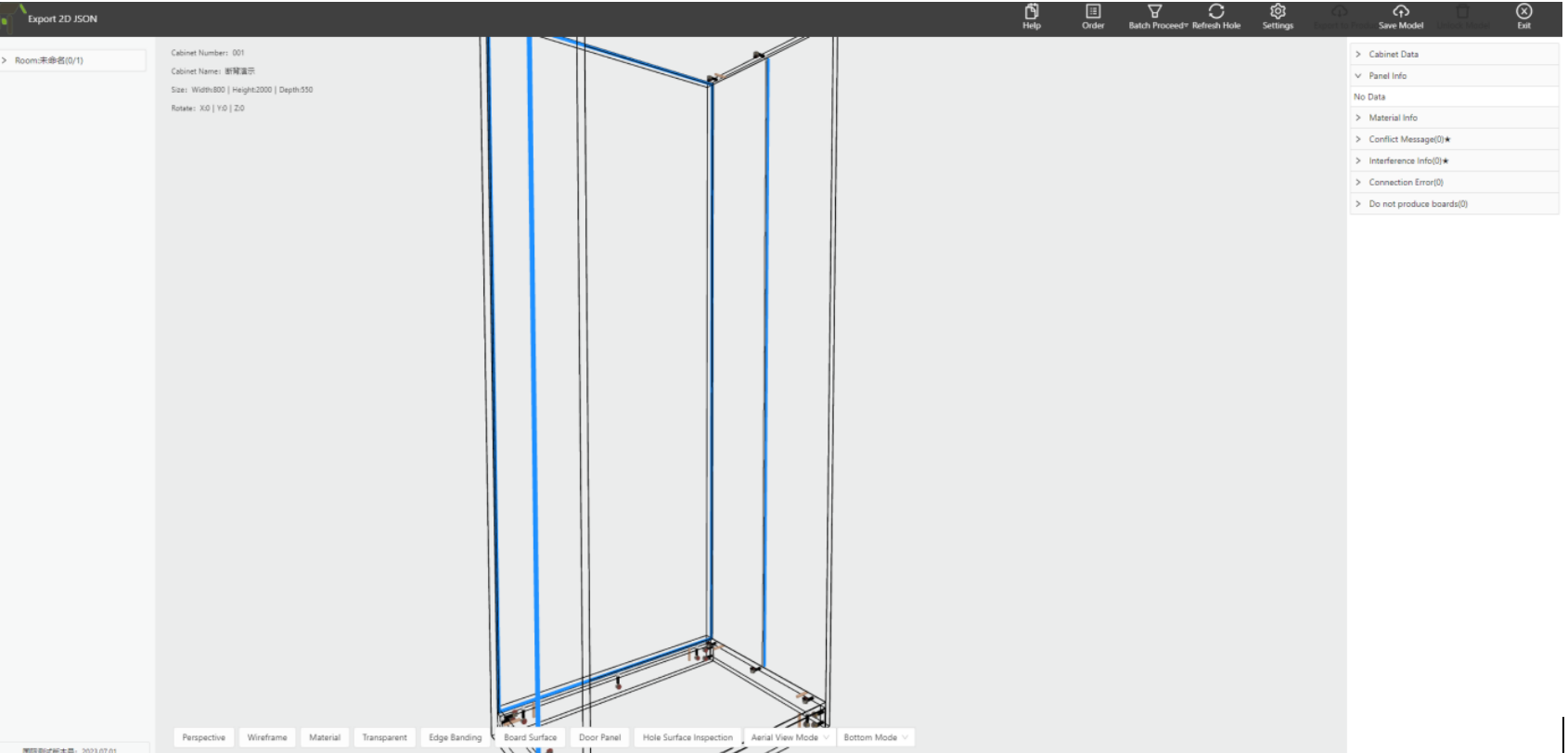
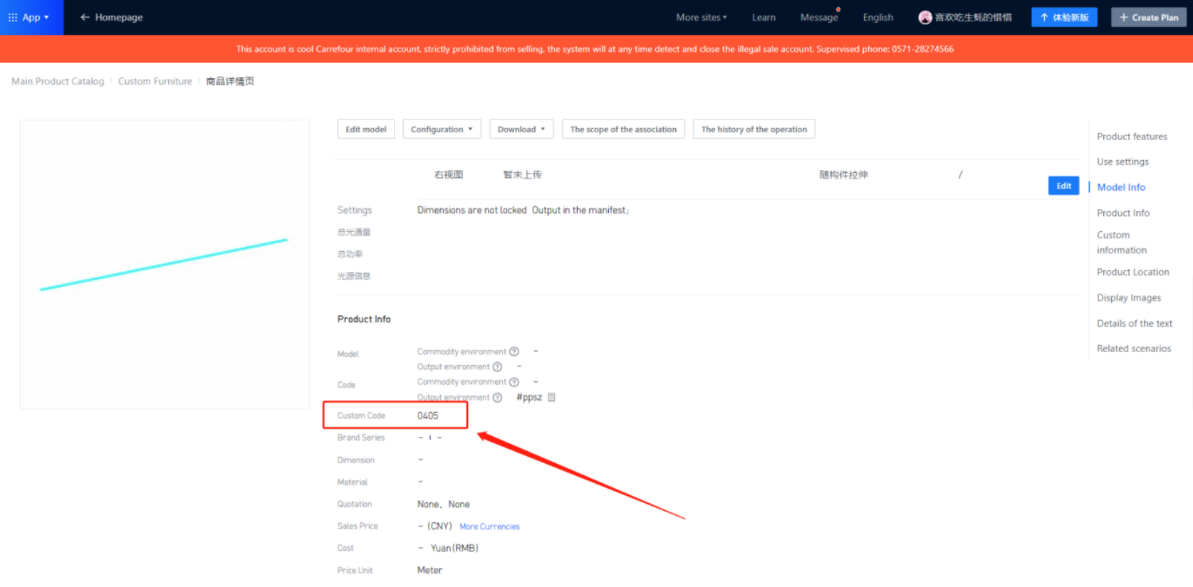
● This section mainly focuses on cabinet hardware connections, which usually consist of factory-standard hardware such as three-in-one connectors, two-in-one connectors, adjustable shelf pins, or other cabinet hardware based on different factory requirements. Additionally, it is necessary to configure this in applet settings. The associated virtual hardware should be custom-coded as "0405," as shown in the following diagram.
4.2 Private Hardware
● Apart from some basic hardware for cabinet connections, there are also private hardware items such as handles and clothes hangers. These hardware items are usually uploaded directly by Coohom backend and will appear in the hardware material list of the applet.
● When uploading the hardware, please fill in the custom code field in the product details page according to the hardware type. For example, use "0405" or "0406" as needed. Currently, virtual hardware and 3D objects are supported (for 3D hardware, please upload them under the "Other Accessories" category)
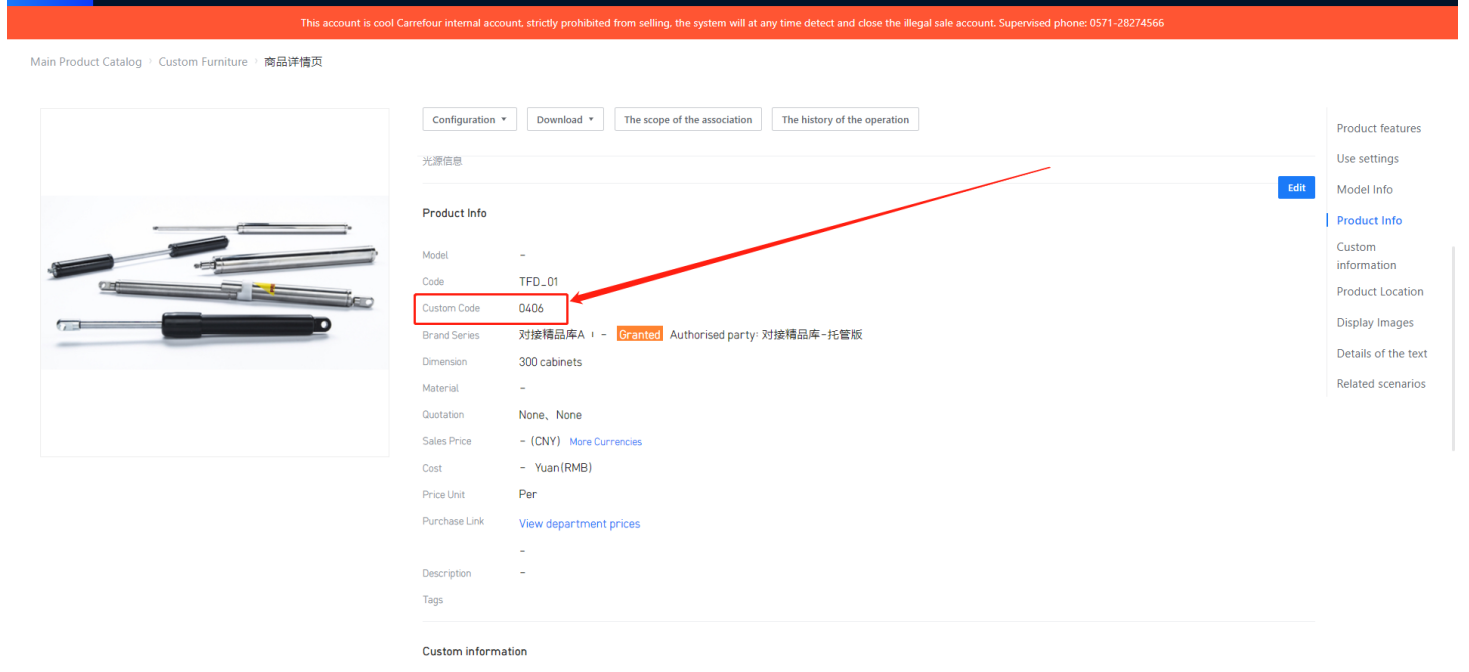
① Hardware unit
● Disassembly Applet reads the hardware product details page "price unit"," hardware specifications ", and reflected in the material list
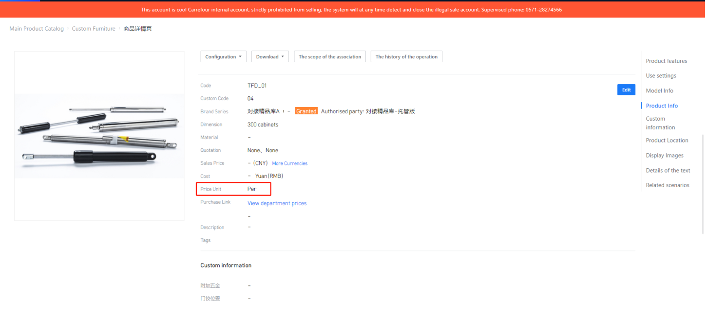
② Hardware specifications
In Coohom, there are two types of hardware: physical hardware and virtual hardware. Physical hardware has specific specifications and dimensions, while virtual hardware can have specifications defined based on their size.
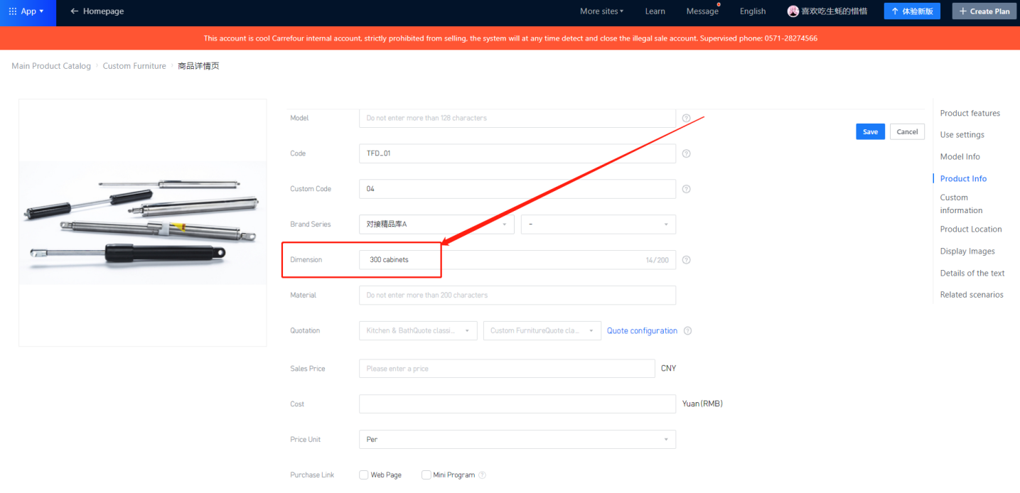
In certain cases, the industry uses different descriptions for specifying hardware attributes, such as using aperture size, etc. For such cases, you can fill in the "Product Size" field in the hardware product details page with the specifications of the hardware, such as "96 holes" or "300 cabinet pull-out basket", etc. The order assistant will reflect this information in the specifications section of the material list
.③ Hardware Grooving
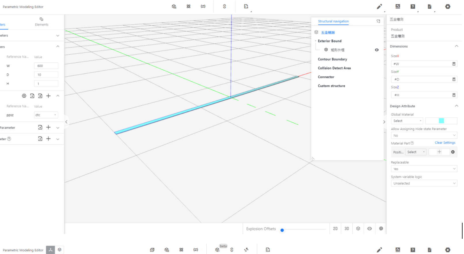
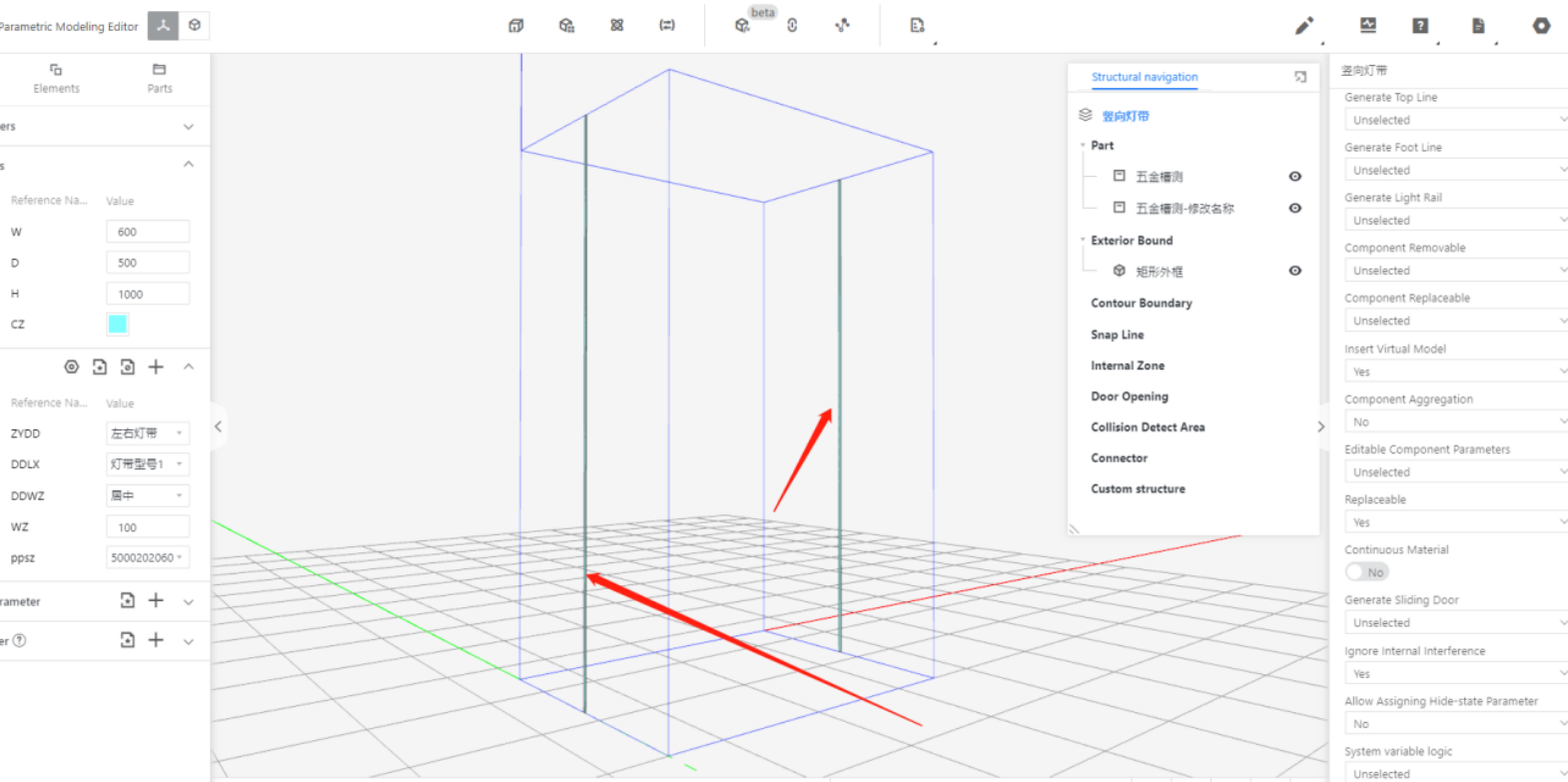
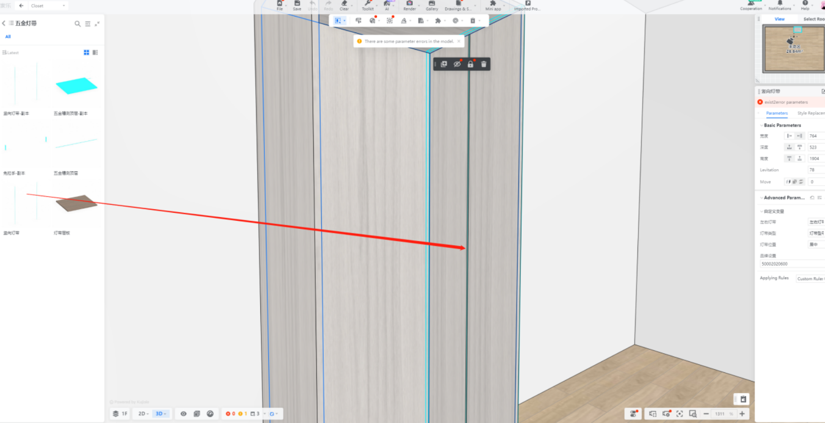
The slotting feature in the order assistant is a unique function for hardware. This hardware requires grooving on the board during processing, such as hardware for LED strips. The overall design scenario is that the designer drags a piece of hardware and attaches it to the panel. The position of the hardware on the board can be adjusted based on parameters.
The order assistant will perform slotting based on this position, the contact specifications between the hardware and the board, and the depth configuration in the order assistant settings. If this hardware requires both slotting and inclusion in the material list, you can fill in the industry category with "0405" or "0406".
You can check the hardware slotting configuration in the order assistant settings.
● Modeling Scenario
In modeling, the ability to rotate the model allows achieving the desired position effect.
-
Design Scenario
Design Scenario
-
Disassembly Display
Disassembly Display
-
Fill In Code: According to the hardware types defined, 0405 refers to one type, while 0406 refers to another type.
Fill In Code: According to the hardware types defined, 0405 refers to one type, while 0406 refers to another type.
4.3 Additional Hardware
4.3.1 Introduction
In the industry, some hardware components require additional hardware to be fully assembled. For example, commonly used handles require screws, and door hinges require screws as well. During the normal production process, these additional hardware components need to be equipped by the factory. However, in the integration process, 3D hardware cannot incorporate other products, making it difficult to reflect this type of hardware in the information during the order integration.
Therefore, as the demand for this requirement from customers gradually increases, the BOM version of the Order Assistant considers using a new solution to represent the layout of such products.
4.3.2 Upload
① Step 1: Upload the corresponding virtual hardware to the enterprise library according to the requirements.
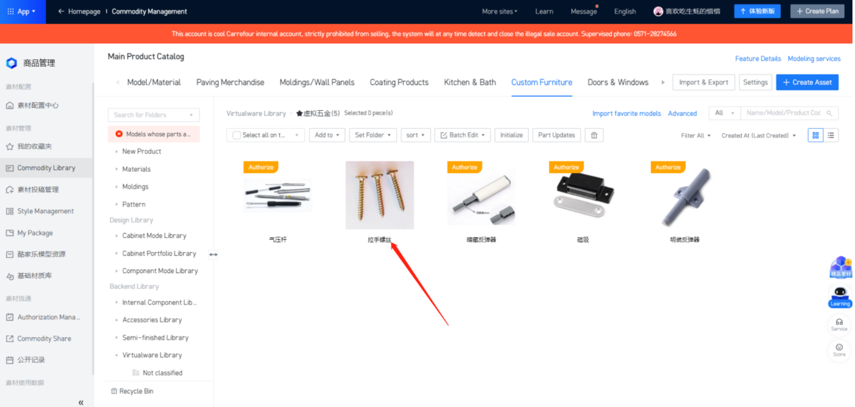
② Step 2: Copy the ID of the virtual hardware.
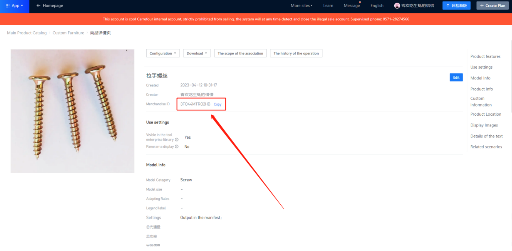
③ Step 3: Open the product that requires additional hardware to be filled in. For this handle, you must enter a custom code.
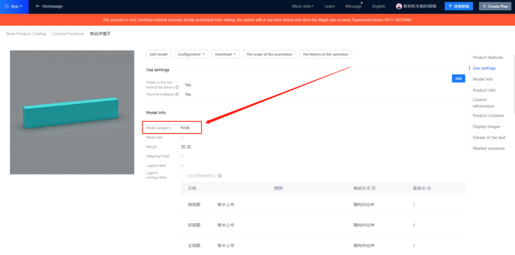
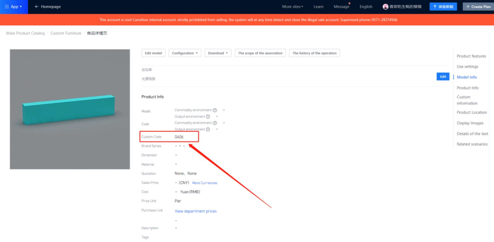
④ Step 4: Fill in the custom field with the ID of the virtual hardware copied earlier.
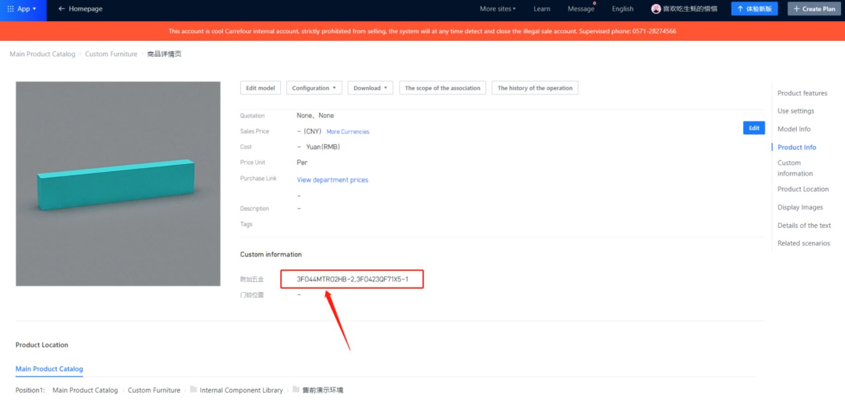
Note: In the custom field, make sure to include the phrase "additional hardware“ as a reference name. Otherwise, it will not be outputted.
③ After we fill in the ID of the additional virtual hardware in the custom field, we also need to attach the quantity and other information, as follows:
Tables can't be imported directly. Please insert an image of your table which can be found here.
Type
3FO44MTRO2HB
-
2
Explanation
Attach the ID of the virtual hardware
Special symbol "-"
Quantity of this hardware
Note:If a hardware need to produce a variety of additional hardware, we only need to add another group of data after a group of information, and then separate with a comma ", "such as: 3FO44mTRO2HB-1,3FO44ABCO2GH-2
4.3.3 Other Question
● As for the handle screw lead hole, it is solved by auxiliary structural parts
● Custom fields, need to add their own
5. Other Products
5.1 Sliding Door Products
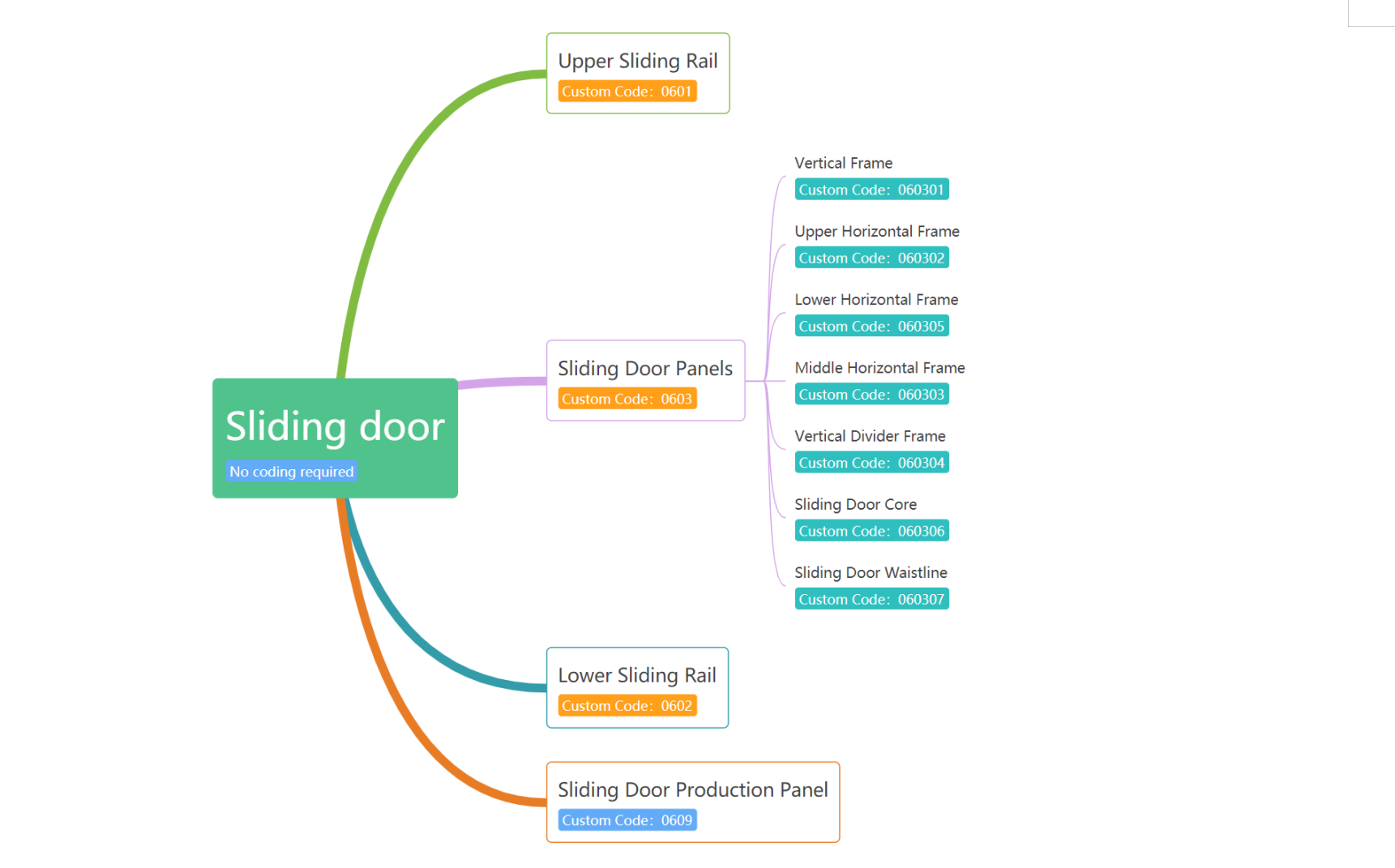
Sliding door products in the applet are directly outputted from the list of materials. They can provide data for sliding door openings, door panels, frames, and core board information. The following are the corresponding custom code contents for each part of the sliding door product.
Note: There is a custom code category "0609" mentioned below. The content will ultimately be involved in production planning and will appear in the sliding door bill of materials. It can also be freely set to appear in the panel bill of materials.
5.2 Molding Types
l Molding products are directly outputted from the bill of materials in the applet. The outputted content includes three types of automatic moldings, Roman columns, Lintel Panel, gallery bridges, and other products. The following are the corresponding custom code contents for each part of the Molding type product:
Tables can't be imported directly. Please insert an image of your table which can be found here.
Door Panel
Industry Category
Code Location
Automatic Molding
0501
Custom code on the cross-section details page
Curved Product Docking
0502
Detailed information can be viewed according to section 5.4
Lintel Panel
0701
Custom code on the product details page
Roman Column
0702
Custom code on the product details page
Gallery Bridge
0505
Custom code on the product details page
5.3 Base Material Information
In the industry, some factories may have different base materials for the same color or may use specific base materials based on different thicknesses. Currently, there are two ways to handle this:
①Carrying base material information directly with the name.
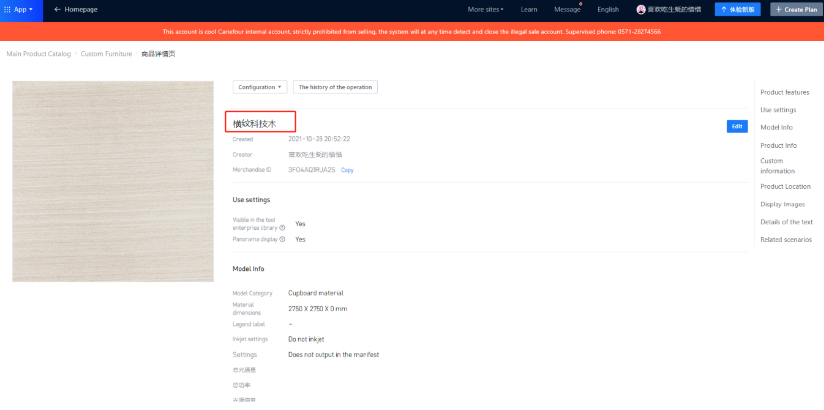
② Adding base material information in the product details page, using the thickness to determine the base material usage.
Note: Only one of the two methods should be used, and they cannot be mixed.
5.4 Curved Products
5.4.1 Description
In the industry, curved products are a common type of special product that requires manual handling. They usually require craftsmen to use strips of panels for manual sprouting, bending and shaping. In the applet, we can output the enlarged dimensions of these strips. The craftsmen can directly take the strip and follow the label for production. For more detailed information, please refer to:
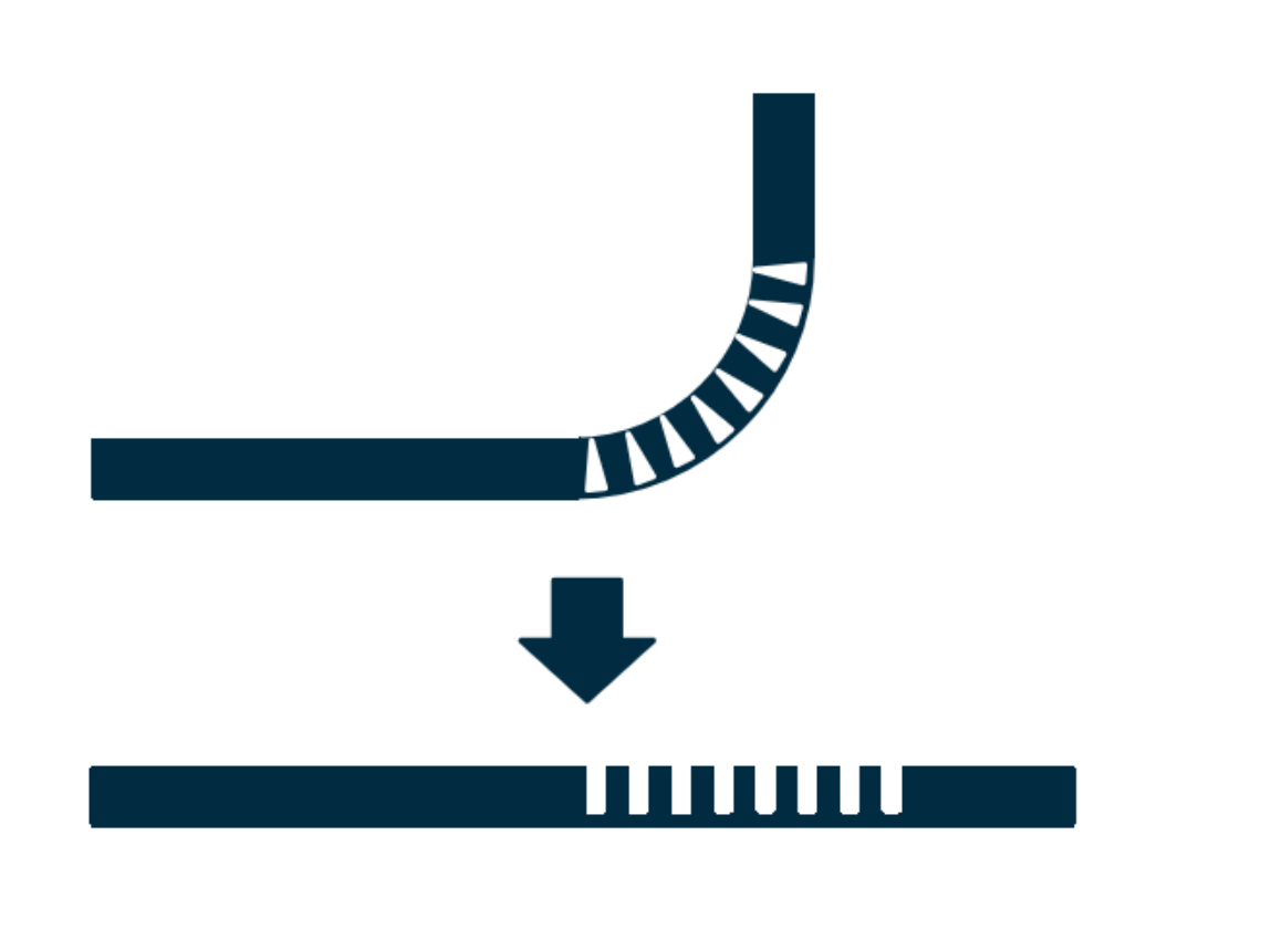
The above figure shows an example of sprouting process, and the corresponding model output formula is: Total Length * Width * Panel Thickness - Arc Length - Length of one straight edge. The final result reflected in the material list is: 750*80*18-220-100.
5.4.2 Production Output of Arc Foot Molding
According to the above description, we use the model information to output the length, arc length, and side length of the arc foot molding. In the actual production scenario, we can transmit data to the processing scenario in several ways.
Tables can't be imported directly. Please insert an image of your table which can be found here.
/
Type
Description
Processing
1
Material List Remarks Display
Read the model number (modelProductNumber)
Provide intuitive inventory information
2
Tag Information Reflected
The layout software loads and reflects based on the disassembly instructions given in the remarks
Provide tag information to facilitate manual processing to eliminate material calculation time. It requires manual cutting and subsequent bending work.
3
Output material data
l According to the specific identification and model information, disassemble the order into the actual arc foot length: Arc Foot Molding Solution
1. The current note information shows 800*70*18-300-200 (with 800 indicating length, 70 indicating width, and 18 indicating thickness).
2. Using specific product codes and the first three digits of the model number, the product can be converted into a board strip. The model number field is “modelProductNumber”.
3. Although the product still appears as an arc-shaped foot molding during disassembly, it will be converted into a board with dimensions of 800*70*18 for production scheduling.
4. In the final production scenario, workers will take the board that meets the requirements for making arc-shaped foot moldings and process it according to the information on the label to produce the finished product.
5. For surplus considerations, such as adding 150 to the finished product size, the formula is (#W+#D-#Yr*2+(#Yr*2*3.14)/4+150)+'x'+#H+'x'+18+'-'+((#Yr*2*3.14)/4)+'-'+(#W-#Yr), where 150 is the incremental value. If no surplus is required, it should not be added.
The necessary materials for making the foot moldings can be provided, and workers only need to complete the subsequent processing.
-
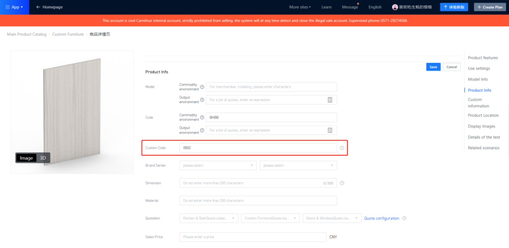
In the circular arc product details page, the custom code should be filled in as: 0502.
In the circular arc product details page, the custom code should be filled in as: 0502.
5.4.3 Circular Arc Array Slot
This product is still being upgraded.
Others
1.Common Problems
Panel does not output
①Check if the custom code is filled in or filled in correctly.
Panel has no holes
①Check if the custom code is filled in.
②Check if the cabinet is a docking library model.
③Check if the configuration is correct or if it is not set to default.
About Slot Increment
①Slot increment: There are two types of slot conditions in the disassembly assistant, one is interference slotting for panels, and the other is hardware slotting. Interference slotting for panels can be further divided into two types, one is with custom code 0201, and the other is with custom code 0202.
Regarding slot increments, when using a panel with custom code 0201, the slots on the passive board will be affected by the slot increment in the disassembly assistant. However, when using a panel with custom code 0202 or when using hardware for slotting, it will not be affected by the slot increment in the disassembly assistant. Therefore, the cooperation between the disassembly assistant and the backend needs to be adjusted according to the actual situation to achieve output coordination.
②For customer 1010, they can set slot width and slot depth increment in KRSDR. Hence, only one of the two places needs to be set. Setting both will cause larger slots to be generated, and not setting any slot will keep the original size. If six-face drilling supports slot increment settings, then neither the applet nor KRSDR needs to set slot increments; instead, it can be set in the six-face drilling.
③For customers other than 1010, if they meet the backend’s slot increment settings, then only one place needs to be set. If neither is set, the six-face drilling support can also adjust the slot increment.
Other Problems
Guidelines for filling in codes:
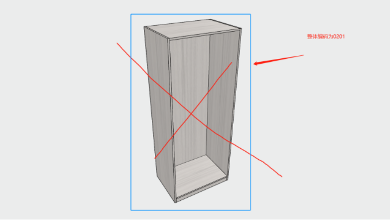
①Remember to fill in the codes for panels, hardware, auxiliary boards, etc., only at the model commodity level on the product details page. Do not fill in the code at the top-level of parametric models. For example:
Tables can't be imported directly. Please insert an image of your table which can be found here.
Wrong
Right
Entity Model Upload
When hardware or slot attachment hardware needs to be uploaded, the true classification only supports uploading via "Other Accessories" or "Functional Parts" methods.
Prohibited Actions
In the base panel, multiple elements are not allowed, nor are 3D hardware allowed. Currently, only elements plus multiple virtual hardware and unfolded elements are permitted.
Model Parameters Mandatory
During modeling, the base panel needs to have the option for passing hidden variables set to "Yes." This setting will directly affect whether certain hidden processes can be successfully written back to the data by the disassembly applet.
Part Parameter Editable
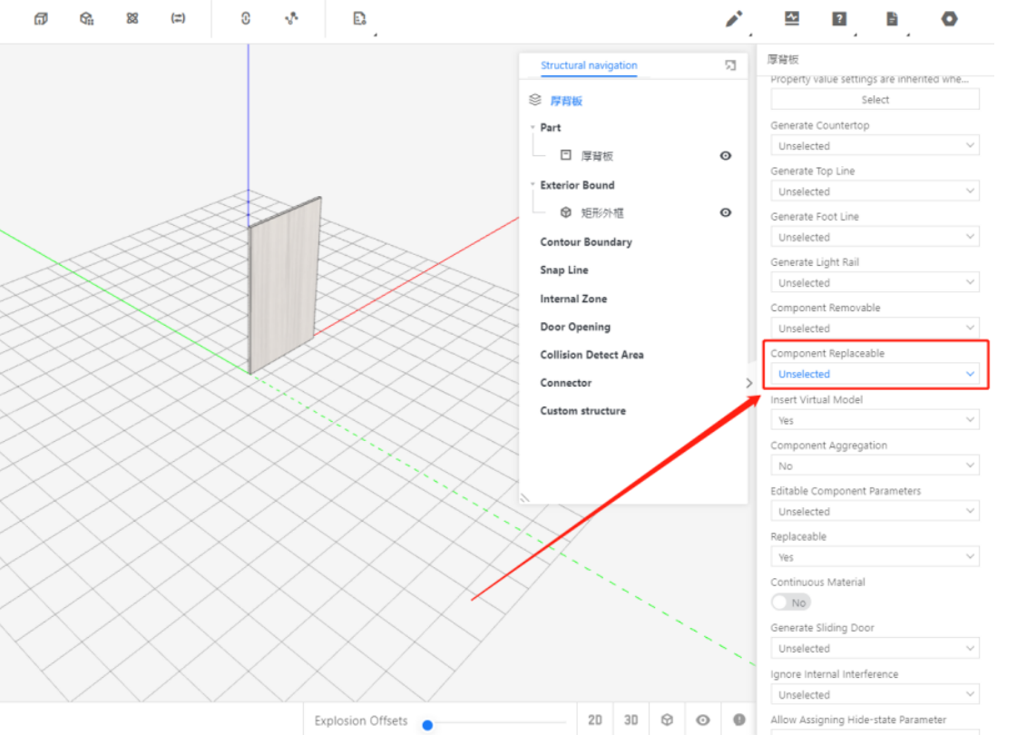
During modeling, the base panel needs to have the option for part parameters editable on the right sidebar of its parent layer. Set it to "Yes." This parameter determines whether parameters such as ET, EC, SBFX, etc. can be written back during the splitting process to provide identification.