1.1.1 Introduction
① Location of applet configuration settings
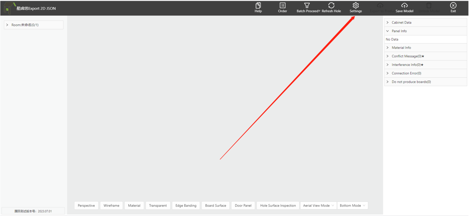

Note: Multiple sets of factory process configurations can be configured under the same account
1.1.2 Configuration Relationship Introduction

① General Configuration: Except for hole position and edge banding, other process setting positions are independently configured;
② Hardware Accessories Setting: The defined position of all connected hardware holes is independently configured and can be downloaded and uploaded;
③ Hardware Hole Layout Rule: The data association position between the Coohom and Applet models is independently configured and can be downloaded and uploaded.
④ Edge Banding Setting: The data association position of edge banding for the Coohom and Applet models is independently configured and can be downloaded and uploaded.
Note: The connection name in ③ should be consistent with the name in ②. For details, please refer to section 3.5 below.
2、Hardware Fitting Settings
1.2.1 Position
Click on "Modify" to enter the configuration.

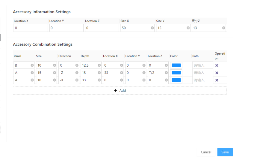
1.2.2 Fittings List
This is primarily used to configure hardware names, display hardware models in the applet, include hardware data in the material list, and provide various other capabilities required in the industry.
For more details, please refer to the content in the table below.
Tables can't be imported directly. Please insert an image of your table which can be found here.
Content List
Fill in Content
Function Details
Fittings
Fill in connection name
The final name will be output as the hardware name in the material list, and it will be called in the hardware hole layout rule to establish the association with the hardware.
Hardware
Fill in the hardware ID
In Coohom, each model will have a unique ID that can be associated here. The applet will eventually call this model for display, and it has specific requirements for the modeling coordinates of hardware models.
Note① :This hardware is only used for disassambly applet display and does not serve as any data or information processing output.
Note② :In this table, the ID column for hardware must not contain duplicate values.
Virtual Hardware
Fill in the virtual hardware ID
In Coohom, each virtual hardware has a unique ID that can be associated here. If this field is filled in applet, it will be recognized as an input and used to calculate the quantity for output.
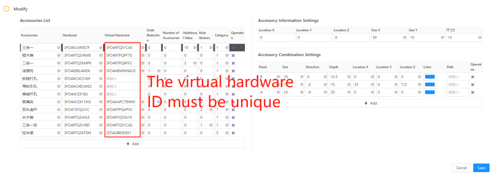
Note:In this table, the ID column for virtual hardware must not contain duplicate values.
Reduce size
Enter reduced size
It is generally used for movable layer boards and glass layer boards. If you input "1" in this field, when generating the cutting list data, the system will deduct the specified reduction value from the four edges of the connected panels. The reduction value will not be applied to edges that do not have connections.
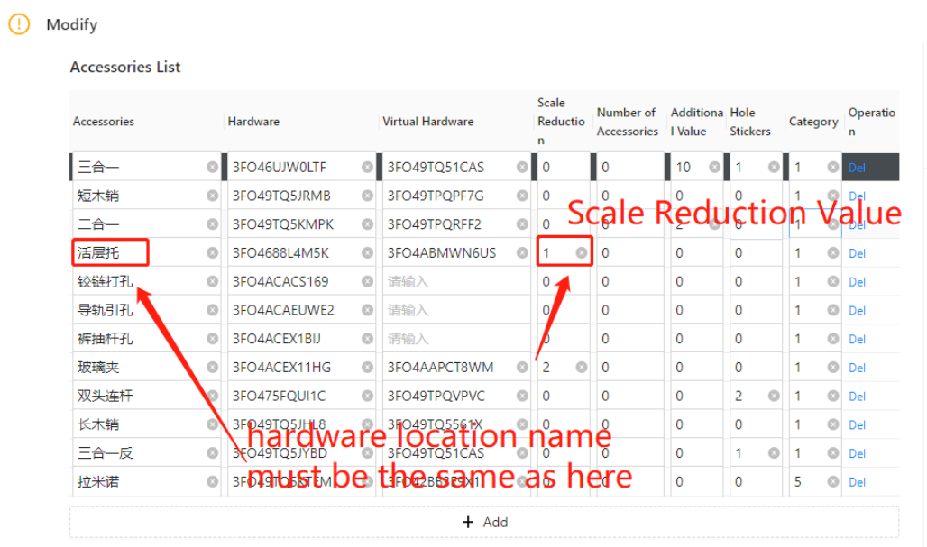
Configuration:
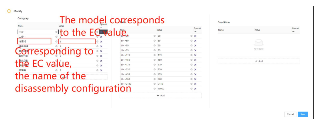
In the hole layout rules, the name preceding the EC value must be identical to the hardware name in the component positioning list. Otherwise, it will become invalid.
Additional Quantity
Fill in additional quantity ratio
In the industry, there are cases where extra hardware fittings are added during distribution. You can simply enter the corresponding ratio here.
For example, if you want to add one extra for every 10 hardware fittings, you can directly write "10". In the final materials list output, for every 10 hardware fittings, one extra will be added. If there were initially 100 fittings, the output will be 110.
Adhesive
Filling coefficient
As shown in the figure, the number of adhesive is filled in 1, and the number of three-in-one in the final hardware single will output the corresponding multiple of adhesive

Type
Value:1:2:3:4:5
The type in this section primarily controls the hardware, and how to applet processes data. For all connector types, such as three-in-one or two-in-one, you can fill in the value "1".
value "2":represents a square slot. For more details, please refer to the hardware slot configuration below (1.3).
value "3" represents a circular slot. For more details, please refer to the hardware slot configuration below (1.3).
value "4" represents an irregular slot. For more details, please refer to the hardware slot configuration below (1.3).
value "5" represents invisible parts. For details, see the following hardware slot configuration (BOM version removal capability).
1.2.3 Fittings Information Setting
①Description
This position is primarily used for adjusting various types of hardware in the display position within the model, along with additional depth for specific types.
Note:Additional depth for specific types refers to the values mentioned above, such as 2 (square groove) and 3 (circular groove) scenes, which can be viewed based on the hardware groove in section 1.3This position is primarily used for adjusting various types of hardware in the display position within the model, along with additional depth for specific types.
② Position XYZ
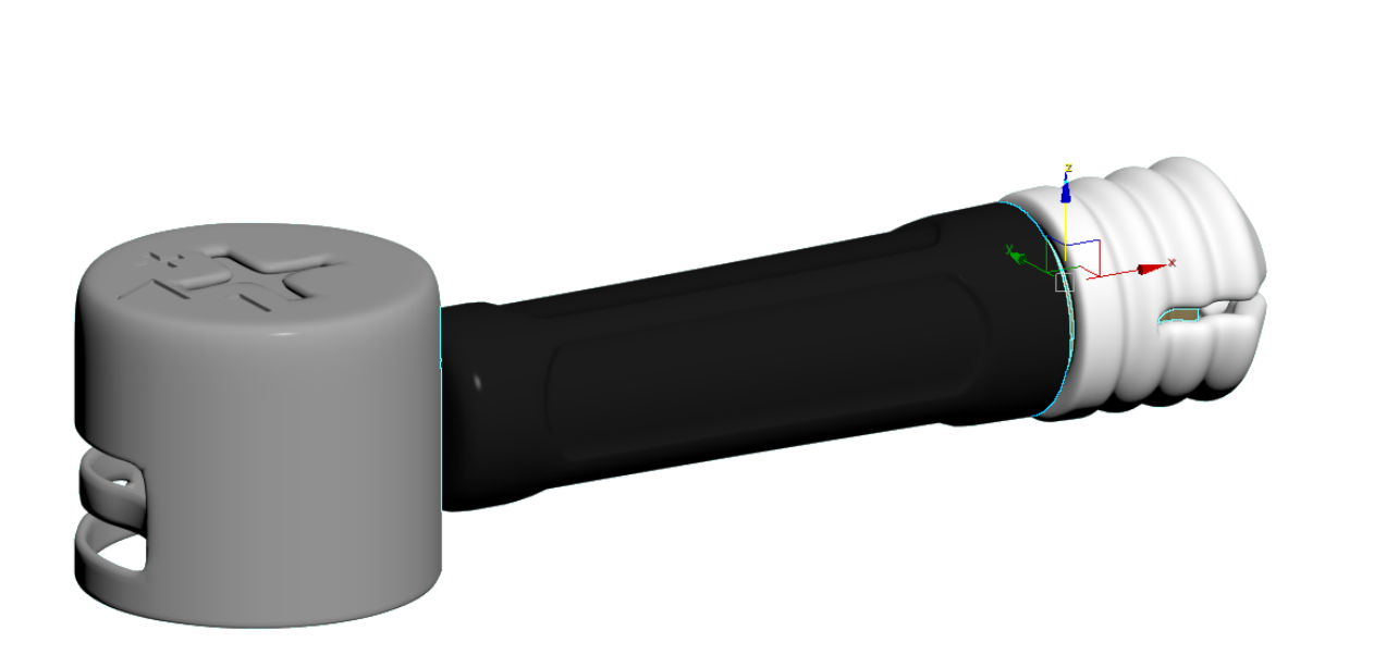
-
As shown in the above image, there are specific requirements for the coordinates when creating our models from 3dMax. During the three-in-one installation, the white pre-embedded component is placed above the side panel, while the black connecting rod is installed above the horizontal board. Therefore, the center point needs to be set as the origin between the black and white components in 3dMax.
As shown in the above image, there are specific requirements for the coordinates when creating our models from 3dMax. During the three-in-one installation, the white pre-embedded component is placed above the side panel, while the black connecting rod is installed above the horizontal board. Therefore, the center point needs to be set as the origin between the black and white components in 3dMax.
-
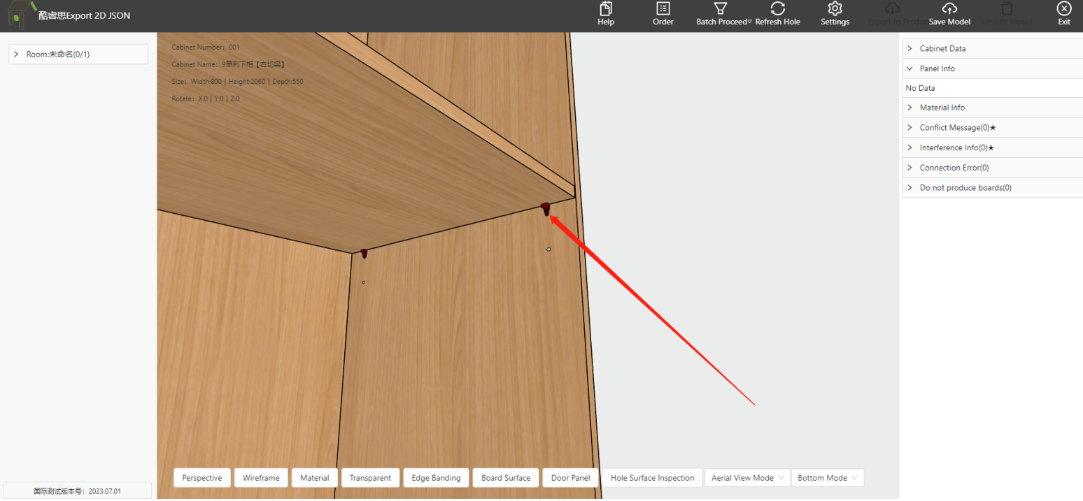
We have completed the above tasks, including model upload, ID filling, and specifying the type. However, for certain hardware components such as two-in-one or movable shelf pins, they are not located at the center of the side panel during installation process. Despite this, when we upload the model, it already has an origin point defined. Therefore, we need to make some position adjustments for these types of hardware components, as shown in the image:
We have completed the above tasks, including model upload, ID filling, and specifying the type. However, for certain hardware components such as two-in-one or movable shelf pins, they are not located at the center of the side panel during installation process. Despite this, when we upload the model, it already has an origin point defined. Therefore, we need to make some position adjustments for these types of hardware components, as shown in the image:
-
The correct installation method for this hardware component is below the panel, so we need to move it along the Z-axis to achieve the desired effect. Please note that the displayed model effect does not represent the actual position of the holes.
The correct installation method for this hardware component is below the panel, so we need to move it along the Z-axis to achieve the desired effect. Please note that the displayed model effect does not represent the actual position of the holes.
③ Size XYZ
l The values of dimensions X, Y, and Z will be written into the bill of materials (BOM) as specifications for this structural hardware. The subsequent material list can obtain the specifications of the structural hardware based on the data from the BOM.
1.2.4 Fittings Combination Settings
1.2.4.1 Description

-
In the industry, there are various types of cabinet connecting hardware, and it is common for each hardware component to undergo a processing step that involves multiple surfaces and hole configurations. For example, in the case of a three-in-one configuration, we would need to set lock plate holes and side panel connecting rod holes on the active board, as well as plug holes on the passive board.
In the industry, there are various types of cabinet connecting hardware, and it is common for each hardware component to undergo a processing step that involves multiple surfaces and hole configurations. For example, in the case of a three-in-one configuration, we would need to set lock plate holes and side panel connecting rod holes on the active board, as well as plug holes on the passive board.
1.2.4.2 Connecting Hardware Definition
-
Connection Fittings Definition
Connection Fittings Definition
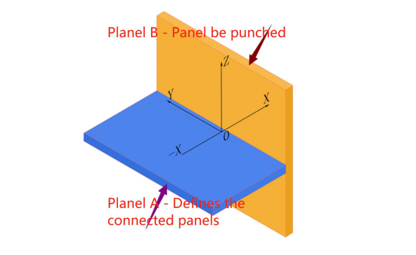
1. The definition of fittings uses a Cartesian coordinate system in three-dimensional space, as shown in the figure above.
2. As shown in the image, A and B are used to represent panels. In this case, A represents the defined connecting panel, while B represents the panel that generates the perpendicular hole. Taking the three-in-one connection as an example, A is defined with a 15mm fastener hole and an 8mm horizontal linkage hole, while B is defined with a 10mm plug hole in the vertical direction.
3. The program generates the connection by default during the design process.
4. It is recommended to first define the vertical holes drilled on panel B.
5. The hole positions defined on the A are based on the initial state of the panel, where the panel is neither rotated nor moved. The thickness of the A is denoted by T by default.
③ Size
-
On panel A or B, the diameter of the drilled hole.
On panel A or B, the diameter of the drilled hole.
④ Direction
-
Define the direction of the drilled hole's exit, determining the direction in which the hole's depth is increased.
Define the direction of the drilled hole's exit, determining the direction in which the hole's depth is increased.
⑤ Depth
-
Based on the above size and direction, customize the punching depth value
Based on the above size and direction, customize the punching depth value
⑥ Position x、y、z
-
Combined with the definition picture of the above connector, the hardware locates the center of the hole surface with 0,0, and Z determines the offset distance of the hole surface
Combined with the definition picture of the above connector, the hardware locates the center of the hole surface with 0,0, and Z determines the offset distance of the hole surface
1.2.4.3 Offset in the thickness direction of the Z component for side holes.
l In the industry, cabinet panels are generally classified into specifications with thicknesses of 18mm, 25mm, and 36mm. In production, different manufacturers have their own process requirements. For example, for a 25mm thick panel, a three-in-one connection may require a 9mm hole offset, while some 25mm panels may require centered drilling. Therefore, in such cases, it is necessary to make adjustments for connection hardware based on different panel thicknesses. For more detailed information, please refer to:
① Common Situation
a. For 18mm thick panels, the standard practice is to drill holes in an evenly distributed manner, which is the most common and standardized process in the industry.
b. For 25mm thick panels
they can be categorized based on different requirements:
l - Centered drilling: With centered drilling, the side holes are typically located at the center position of the panel thickness. The depth of the lock pin hole is generally (thickness/2) + 4.5.
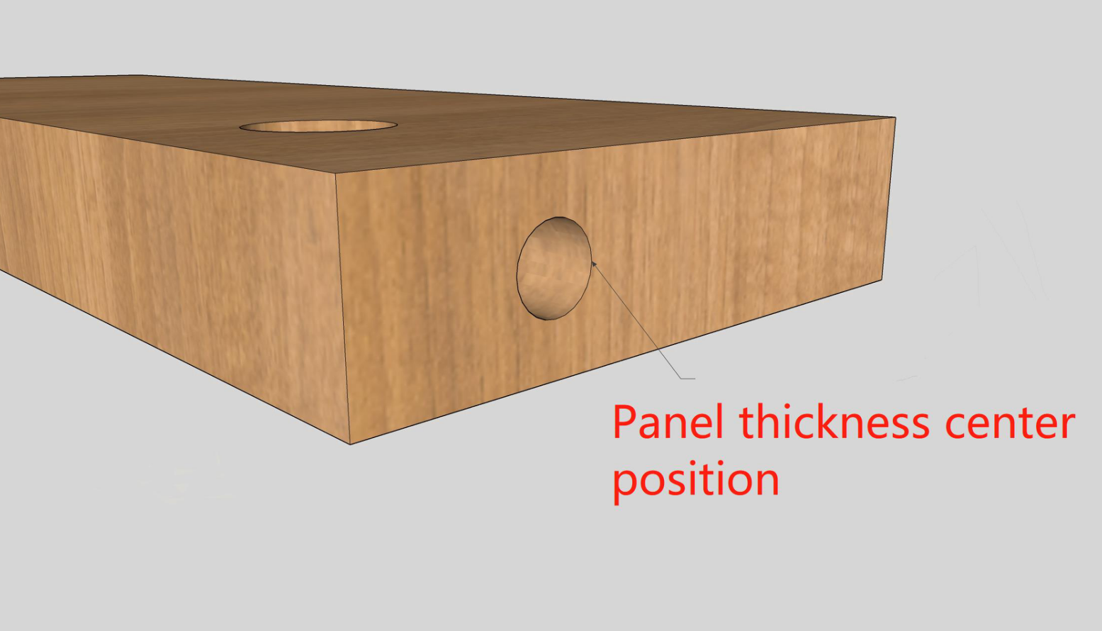
-
Drilling with a 9mm hole offset: A 9mm hole offset means that, with the exit face as the reference, a side hole is drilled at a position 9mm below. The depth of the lock pin hole remains the same as that for the 18mm thick panels, which is approximately 9 + 4.5.
Drilling with a 9mm hole offset: A 9mm hole offset means that, with the exit face as the reference, a side hole is drilled at a position 9mm below. The depth of the lock pin hole remains the same as that for the 18mm thick panels, which is approximately 9 + 4.5.
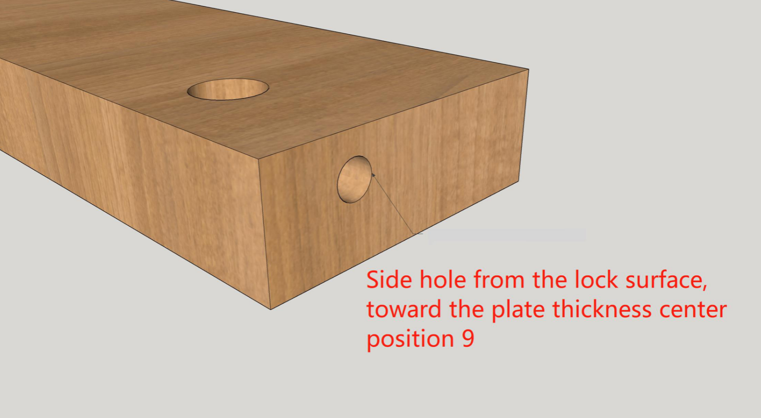
c. The same principles of 36mm and 25mm thick panels. When drilling with centered holes, the depth of the lock pin hole is approximately around 22mm.
Note: Regardless of the position of the side holes on the active panel, the hole positions on the passive panel need to be perfectly aligned with the center of the side holes on the active component. Therefore, it is necessary to configure the settings in the applet program according to the specific process requirements.
The following are the specific configuration settings:
② Hole Position Setting
a. Hardware Common Setting
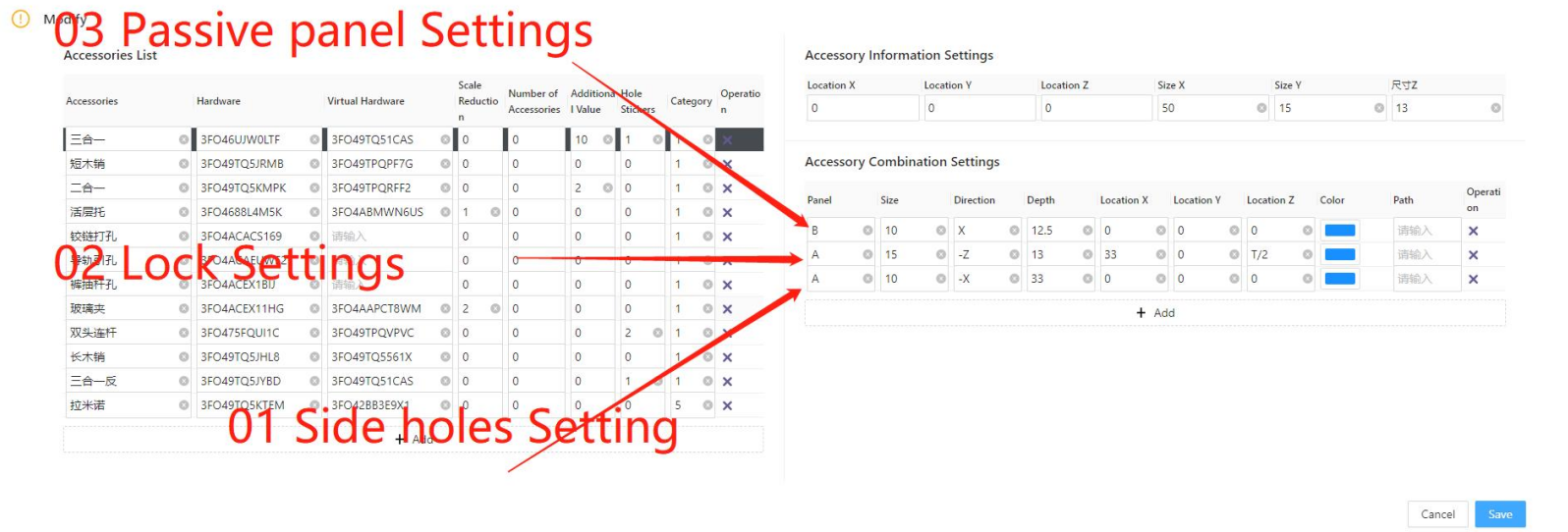
①:Panel 01 is set as the side hole exit mode of the active panel, and the connecting rod in the three-in-one is installed during the installation process. In this text, it is necessary to write its thickness hole exit rule, which is the position Z in the figure
② : Panel 02 is set as the empty hole mode of the lock pin outlet mode, and the eccentric wheel in the three-in-one is installed during the installation. In this paper, the depth value of the lock pin hole needs to be determined according to different panel thicknesses, that is, the depth in the figure
③ : Panel 03 is set as the passive panel outlet mode, and the threaded hole of the connecting rod (embedded part hole) in the three-in-one is generally installed during the installation process. In this paper, the value of the embedded part hole needs to be judged according to different panel thickness, and the purpose is to coincide with the center of the side hole of the 01-panel
b. Example
Note:
Centering: In the applet settings, it is considered as 0. A value of 0 represents the position at the center of the board thickness.
Offset 9: Offset 9 is commonly used for 25mm or 36mm boards, it should be set to T/2-9, which means placing the reference point on the board surface and shifting it down by 9mm for positioning.
Example:
Conditions: 18 panel is drilled in the center, 25 panel is drilled in the off-9 (T==22)OR(T==25)? (T/2-9):0
Panel 01 Formula: (T==25)? (T/2-9):0 Explanation: When the thickness of the panel is 25, the side hole is offset 9, otherwise, it is center drilling
Panel 02 Formula:Directly provide 13.5 Explanation: Since it is considered as an offset of 9 for drilling, the value should be written in its own standard format. In this case, it can also be calculated using a formula.
Panel 03 Formula:Same as “Panel 01 Formula”
1.2.4.4 Offset In Y Direction For Side Holes
① Commen Situation
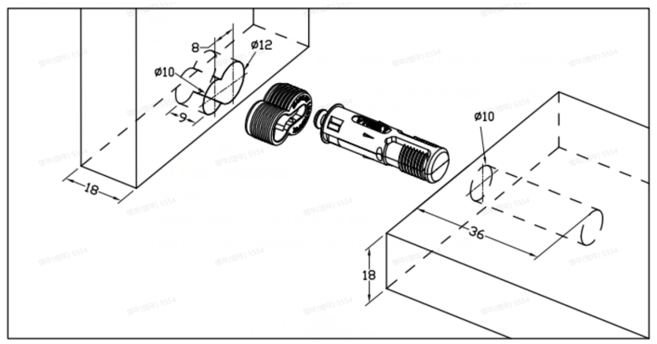
Some hardware fitting in certain structures require multiple holes on the same surface. It can be analyzed as a side hole on the active panel, but the passive panel is composed of two holes, then it can be disassembled as:
Panel A: One side hole with a diameter of 10 and a depth of 36.
Panel B with two holes:
① Diameter: 12, Depth: 9
② Diameter: 10, Depth: 9
The center-to-center distance between these two holes is 8.

② Holes Position
According to the above, we need to configure this fitting as:

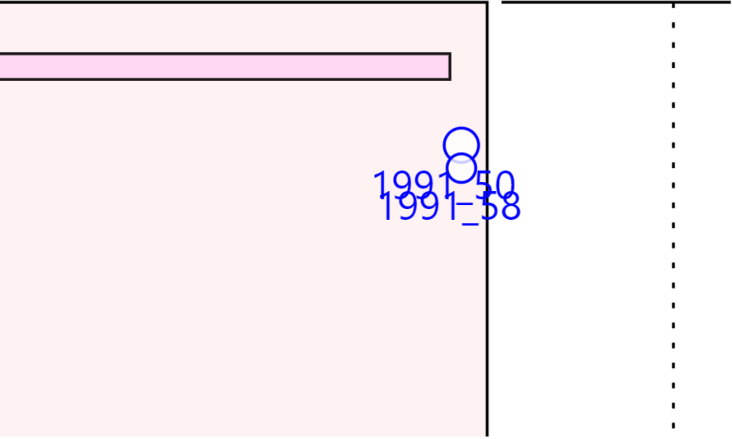
Note: For holes that require offset, the offset distance should be filled in both the X and Y positions with the same value. The sign (+/-) of the value determines the direction of the Y-axis offset. Positive value indicates forward, while a negative value indicates backward.
3、Hardware Slot Configuration
1.3.1 Hardware Slot Explanation
In the industry, there are many companies that use hardware such as strips and concealed handles, which typically require slots to be cut on the panel for installation. In Coohom, there are two ways to achieve this during the production output:
l Option 1: Create an auxiliary board and use the interference slot principle to achieve the required specifications by referring to the component docking technical standards;
l Option 2: Configure the slot in the applet by using a 3D model that generates collision surfaces. The slot type, size, and depth are determined based on the collision surface.
1.3.2 Hardware Slot Configuration
① Upload a 3D model that will generate collision surfaces during the design proces;
② In applet configuration, fill in the Product ID of the 3D model to ensure that the hardware slot matches the actual specifications of the hardware;
③ Define the data type for the hardware slot. Use type 1 for connecting hardware, type 2 for rectangular slots, type 3 for circular slots, type 4 for irregular slots, and type 5 for hidden component slots. Fill in the corresponding type value based on the required slot shape;
④ In the fitting information settings on the right side, fill in the corresponding hardware slot depth in the Z position;
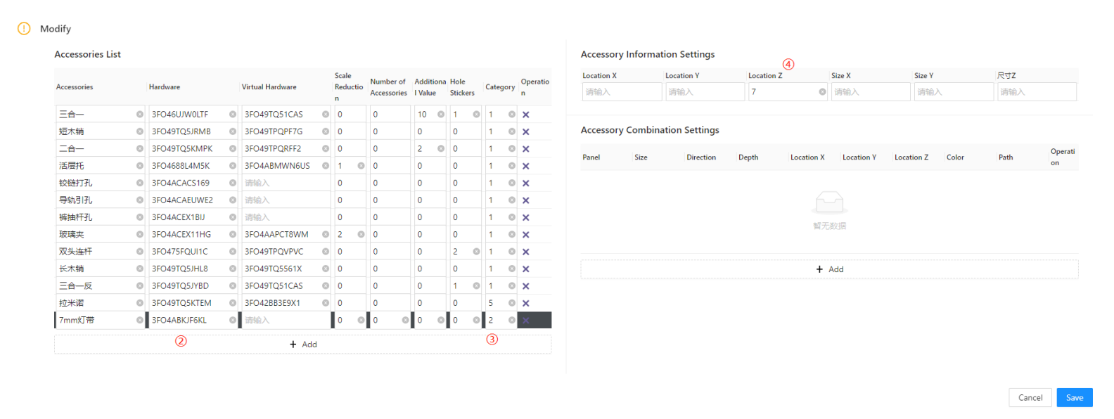
Note:
① In applet, the slot width and depth increments are not calculated for hardware slots. When the type is circular slot, the diameter will be defined as the minimum value of the length and width of the corresponding 3D model.
② When the required slot length and width or the specifications of the circular slot are less than 10, at least one side of the 3D model should have a length greater than or equal to 10. The other side can be set to the required slot width or the diameter of the circular slot. For example, if a diameter of 5 millimeters is needed for a circular slot, the 3D model dimensions should be written as 10*5. The system will define the diameter of the circle based on the minimum value of the two sides.
4、Hidden Condition Output
Hidden parts in the BOM disassembly, the overall implementation is as follows:

In disassembly software, the core information of the hidden part such as its name, slot specifications, orientation, etc., is written into the BOM. As for how this hidden component integrates with the layout and other systems, it is maintained by the ecosystem based on the core information in the BOM. In the applet configuration, we only need to configure this information.
1.4.1 Hardware Fitting Information
-
In the disassembly configuration, the hardware type is fixed as 5, then the system will write the accessory according to the standard defined by the hidden part when writing data.
In the disassembly configuration, the hardware type is fixed as 5, then the system will write the accessory according to the standard defined by the hidden part when writing data.
-
The fitting name will be written into the BOM according to the previously filled.
The fitting name will be written into the BOM according to the previously filled.
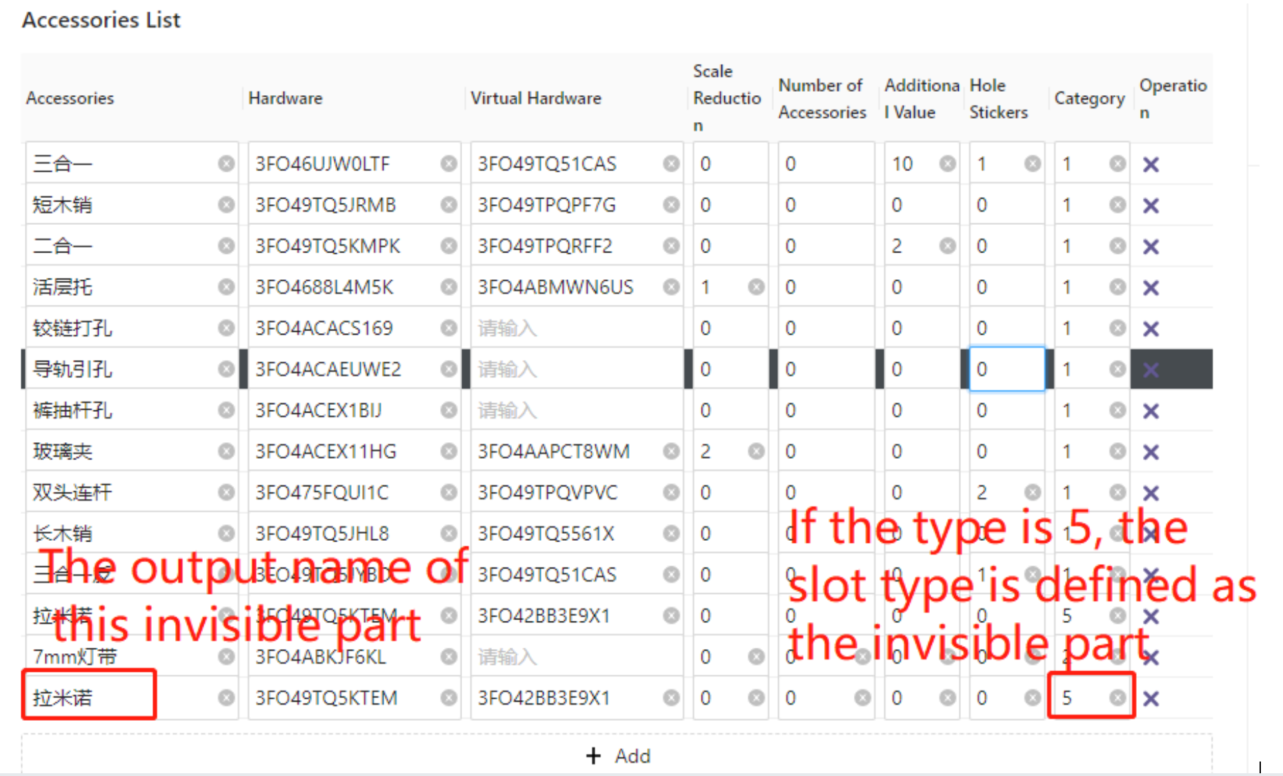
1.4.2 Fitting Slots Definition
After completing the information filling for section 4.1, we also need to provide the ecological software with information about the hidden slot. This information includes the slot width, slot depth, slotting direction on either A or B panel, and the slot length from start to finish.

1.4.3 Tips
The configuration of hidden parts in applet only represents the ability to configure core information, but it does not mean that production is possible once configured. The production information depends on whether the backend ecological software is integrated with the hidden parts in the BOM (Bill of Materials), as well as whether the subsequent equipment in the ecological software can be connected for processing and other factors.
5、Edge Banding Configuration
In the disassembly Assistant, the edge banding docking method and component docking standard use the same approach. The name is filled in as "Used in Disassembly Assistant" and corresponds to the displayed name of the edge banding for the corresponding panel. The value is determined by the ET output values of the four edges of the board, and the thickness is based on the actual edge thickness value. This final calculation is included in the production data.

Note 1:Support negative thickness edge banding data output.
Note2:The pre-milling value here represents the actual edge banding thickness, which is equal to the edge banding thickness minus the pre-milling. This applies to all edges and will be generated accordingly.
6、Positioning Rules
1.6.1 Positioning Rules Introduction
In many ecological software, there is usually an option to set the connection type for the panels. This allows the panels to be associated with holes based on the specified connection type and rules regarding which edge and how many holes will be generated.
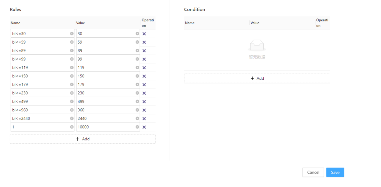
1.6.2 Type
In the type setting, we mainly fill in the EC value for panel connections provided by Coohom and assign a corresponding name to this value.
① Name: This name is not associated with any hole data or other information. It is only used to display the corresponding connection name when clicking on the panel in applet.
② Value: The value content is determined by the database creator when modeling the panel connection types based on the technical standard for component docking. It involves assigning values to each edge (EC1 to EC4) in the JSON file. In the applet configuration, you only need to fill in the connection type corresponding to the value according to the defined connection standards set by the database creator.
Note:For continuous connections, it is a type of double-headed rod connection commonly used in the industry. When configuring it in applet, the name should be fixed and cannot be changed.
1.6.3 Rules
In the rules, we primarily fill in the range of the hole edge for the panels. During the disassembly process, when selecting the corresponding connection type for a panel edge, the specified connection type will follow the edge length range provided here to determine the hole conditions for that particular edge.
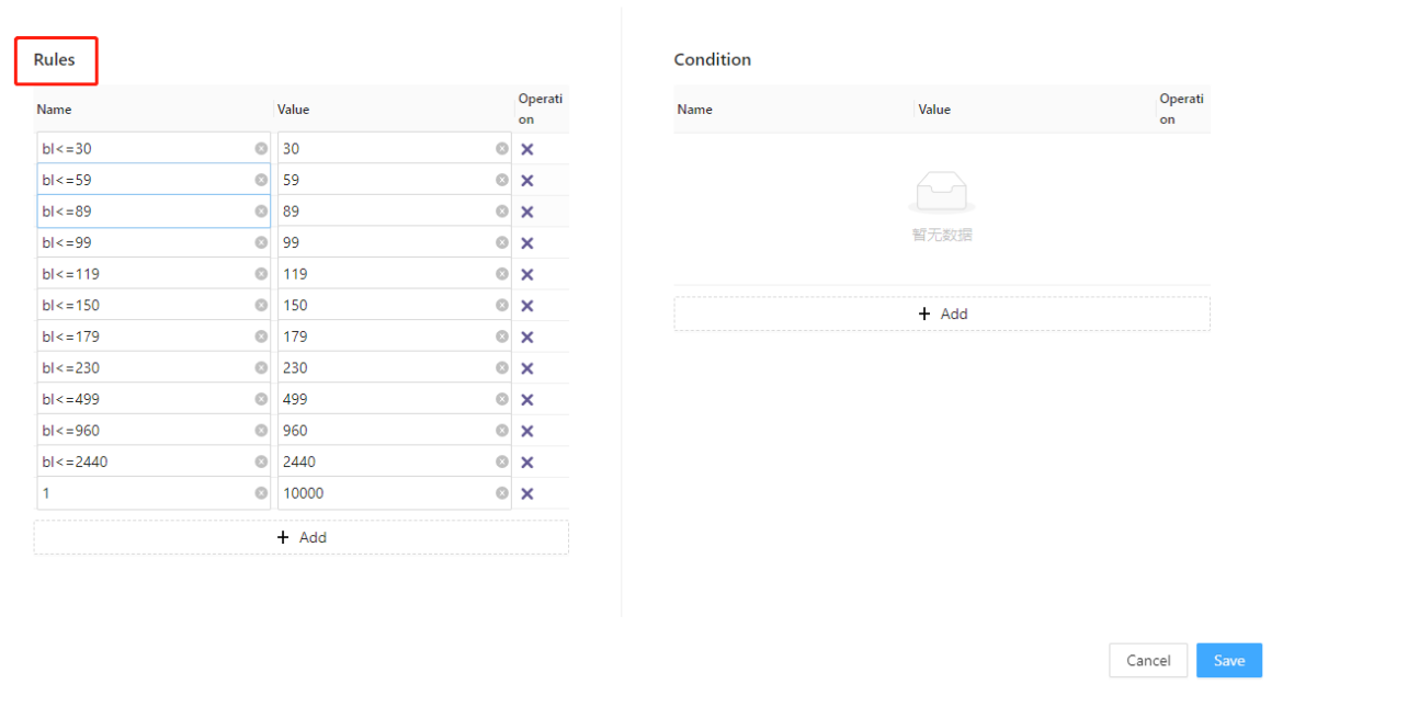
① Name:Primarily describes the range of this value. It does not have any direct association with hole layout data during the hole drilling process.
② Value:It will form in pairs to an range;
-
Case Condition1 :179-230
Case Condition1 :179-230
【Description:179>bl≤230,defining the hole layout method for panel edges with a length greater than 179 and less than or equal to 230 as...】
-
Case Condition2 :230-499
Case Condition2 :230-499
【Description:230>bl≤499,definitingthe hole layout method for panel edges with a length greater than 230 and less than or equal to 490 as....】
-
Other similar cases can be defined accordingly.......
Other similar cases can be defined accordingly.......
Note:The values for each pair of ranges should be filled in from top to bottom in ascending order. It is important to ensure that the order is strictly maintained and not mixed up.
1.6.4 Conditions
The content in the conditions primarily includes filling in the connection component name and the hole positioning values for the panel edge ranges. This allows for matching the corresponding edge length when selecting a specific connection in the applet. It also determines which hardware components will be used within that edge length and specifies their positions based on the value data provided in the conditions.
① Name:The names here should be associated with the names in the fitting list. If the name is not properly associated, it will not match the corresponding hardware fitting.
② Value:The number of hardware fitting required in the side length corresponds to the values provided. Based on the entered values, the corresponding position information for the hardware accessories in the side length is calculated and output.
-
For example:
For example:
- Name: Three-in-One
- Values: -50, 0, 50
-
Description:In the panel's corresponding edge connection, there is a Three-in-One fitting. Its positions are as follows: one Three-in-One located 50 units from the front, one Three-in-One centered, and one Three-in-One located 50 units from the back.
Description:In the panel's corresponding edge connection, there is a Three-in-One fitting. Its positions are as follows: one Three-in-One located 50 units from the front, one Three-in-One centered, and one Three-in-One located 50 units from the back.
-
With the above description, the hole layout for the Three-in-One fitting is completed. If you need to add a Three-in-One fitting with wood shaving, simply click to add another row of data and specify the hole information for the wood-shaving fitting below.
With the above description, the hole layout for the Three-in-One fitting is completed. If you need to add a Three-in-One fitting with wood shaving, simply click to add another row of data and specify the hole information for the wood-shaving fitting below.
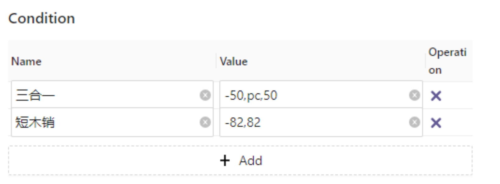
Note: Positive numbers represent forward direction, negative numbers represent backward direction, and 0 represents the center. This is a hole layout method. In the industry, there are other methods such as backward-forward and forward-backward layouts based on multiples of 32. These methods require the use of certain calculation operators, summarized as follows:
Tables can't be imported directly. Please insert an image of your table which can be found here.
operator
Definition
Positive numbers
forward direction position
Negative numbers
backward direction position
bl
panel edge length:bl-50
pa
backward direction:pa+50
pb
forward direction:pb-50
pc
center point
floor
round down
ceil
round up
round
rounding half up
sqrt
extraction of a root
Note:When a single hole is drilled on one side, the central hole only supports writing in PC.
7、Base Material Configuration

1.7.1 Description
In applet, it is possible to configure the base material for panel. We just need to add the base materials that the factory has in the substrate configuration. During the final process of splitting the order, when clicking on a panel, the material selection information displayed will be based on the configured base material information.

Note:Under normal situation, if there is a need to change the base material information in an order, it should be handled by the designer using the design tools to replace the material. If the disassembly staff have not received such notification, it is advisable not to make any unauthorized modifications on their own.
1.7.2 Applet Base Material Docking
Reference:5.4.3 Base Material Information Content
8、Other General Configurations
1.8.1 Slot Adjustment

l In the industry, the common process in factories for backplate installation is to use the method of installing thin backplates into slots. For ease of installation, the slots are generally slightly wider than the actual thickness of the backplate. For example, if the backplate thickness is 9mm, the slot width would be designed as 10mm. To avoid errors during production that could result in shallow slot depths or other issues leading to loose-fitting backplate positions, the slot depth is typically enlarged in the program based on the model's slot depth.
l The above explanation covers slot width and slot depth. In the industry, there is another scenario regarding the selection of slotting tools for backplate slots. In most factories, when the backplate is 9mm thick, a 10mm wide slot is made. However, if the milling tool on the equipment is only 6mm, it would require two passes to complete the slotting process. In this case, the corners of the slot would have sufficient space to accommodate the backplate. However, some factories use a 10mm slotting tool for a 10mm slot, allowing the slotting to be completed in a single pass. However, in this case, the corner arcs of the slot are larger. To facilitate backplate installation, the slot length needs to be extended. Therefore, in such situations, it is important to set a reasonable value for extending the slot length in the appropriate position in the provided image.
Tables can't be imported directly. Please insert an image of your table which can be found here.
Case:6mm milling tool,two times
Case:10mm milling tool,one time
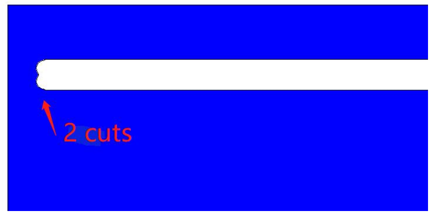
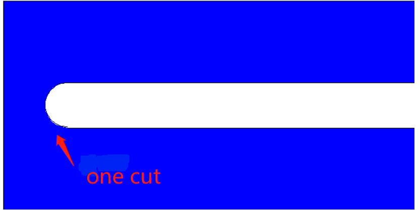
Note:
Slot Width & Slot Depth
① In applet, based on the docking of the panel, it is necessary to fill in the corresponding custom code. The custom code will distinguish the panel into production type and auxiliary type.
② In applet, the slot increment also relates to these panel types. When the panel is of production type 0201, during the output of dismantling data, the slot increment for this panel will be calculated. The auxiliary panels 0202 and 3D hardware slots do not calculate the slot increment.
Note: For panels of type 0201, the increment is enlarged on both sides of the slot.
③ Some backend software also allows setting the slot increment for panels. Remember that if it is set in the backend software, it needs to be disabled in applet. Otherwise, there will be double the increment. It is only necessary to ensure that one of them is set.
Slot Length
① In applet, regarding slot elongation, it only applies to slots generated for 0201 panels. It is invalid for all 0202, 04 hardware slots, and 04 panel hardware slots. For these products, the dimensions of the slot width, depth, and length are determined by their specifications.
1.8.2 Avoidance of Through-Hole
There are multiple production processes in the industry, among which through-hole refers to the situation where a vertical panel exists on both sides of a panel, and the positions are basically the same. This can lead to collision during the generation of connecting components. Some factories specify hole avoidance in their process standards for convenience and stability during installation, while most customers' processes do not adopt avoidance.

① Click the "Avoidance" button in the project to meet the above description of the relevant panel connection, among which there is a three-in-one connection, the three-in-one connector will be avoided, and the step length is 16.
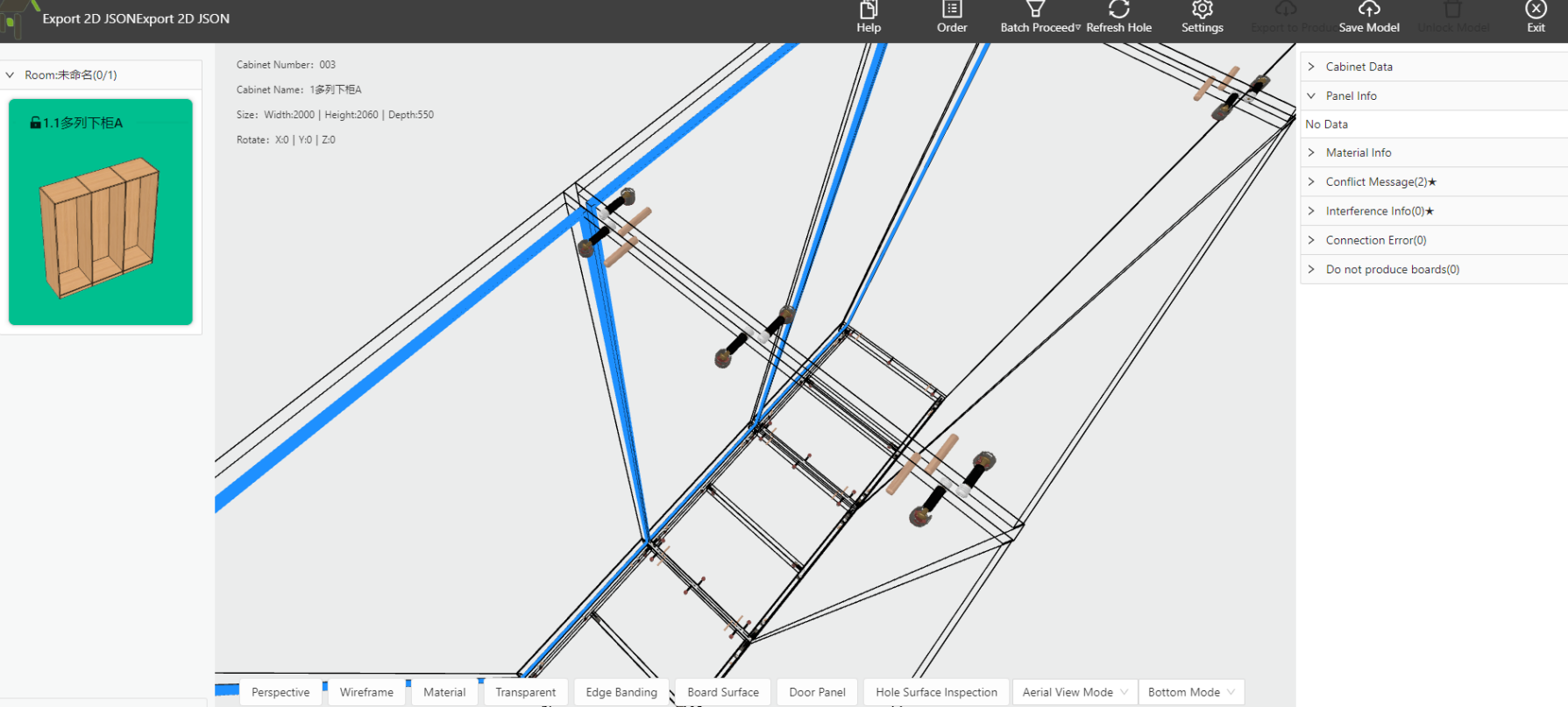
② If avoidance is not enabled, all hardware will not avoidance when there are through-holes.
Note:Avoidance of through-holes can be configured individually for each setting.
1.8.3 Inner Corner Hole Creation
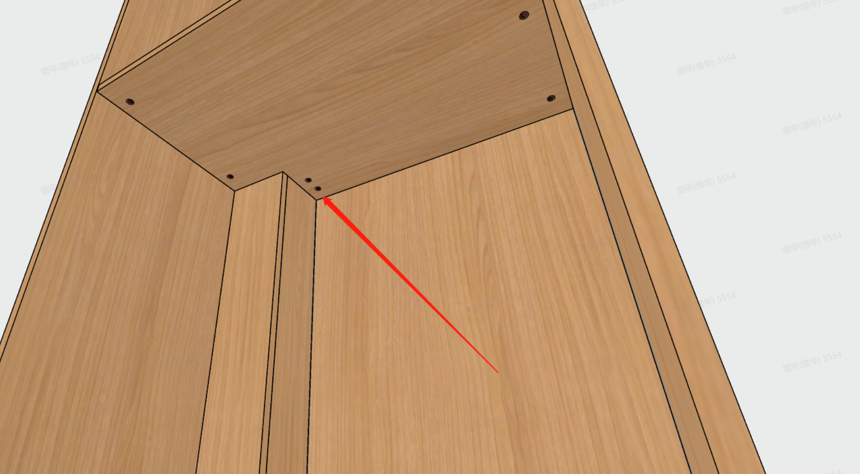
When there are corner cuts on the cabinet, whether holes are generated at the corner cut positions is another non-standard practice in the industry. Most factories still choose to create holes, while some factories may choose not to create holes. Therefore, if you need holes at the corner cuts, simply click on "Generate" to enable it.

① Effect
② No Effect
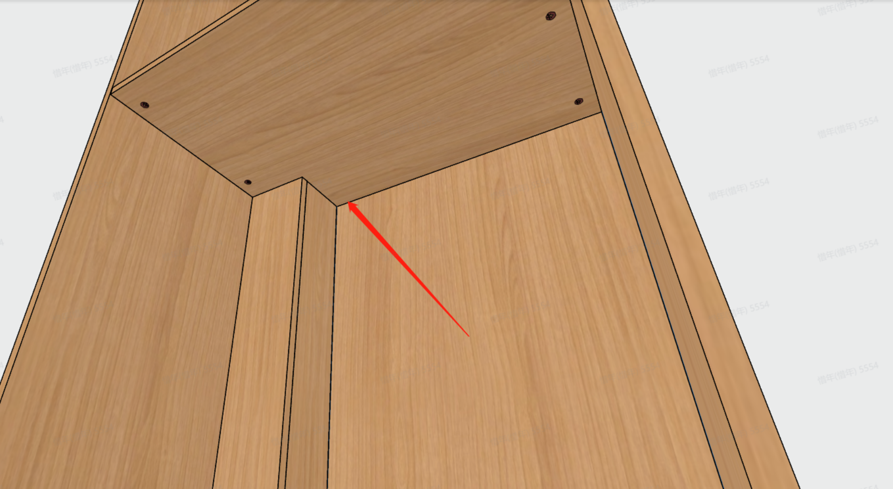
1.8.4 Double-head Connection Hole
Description:A double-head connection hole is typically used in scenarios where two panel collide on their edge but there is no perpendicular panel at the collision point on either one or both of the panels. Some factories use special connectors to join the boards in such cases, while others incorporate this structural technique as a default process to save material. Therefore, the corresponding capability has been developed in applet to solve this particular situation.

Condition:Double-head connecting rods, in applet uses default name, and this cannot be modified in any scenario. Additionally, for a continuity connection to be generated, both panels must collide on their edge surfaces, and the collision edges of both board piece panels must be selected as default type.
The following are the three usage scenarios:
① Not generated: Under any circumstances or conditions, applet does not generate continuity connections;
② Default generation: In the applet, when the conditions for a continuity connection are met, it will automatically generate the continuity connection.
③ Rule-based generation: After meeting the conditions for a continuity connection, applet will not generate it automatically. Instead, the user needs to click on both board pieces and select the corresponding edges as "Continuity Connection" to generate the connection.
1.8.5 Conflict Holes
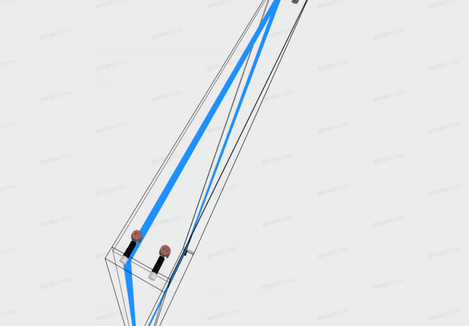
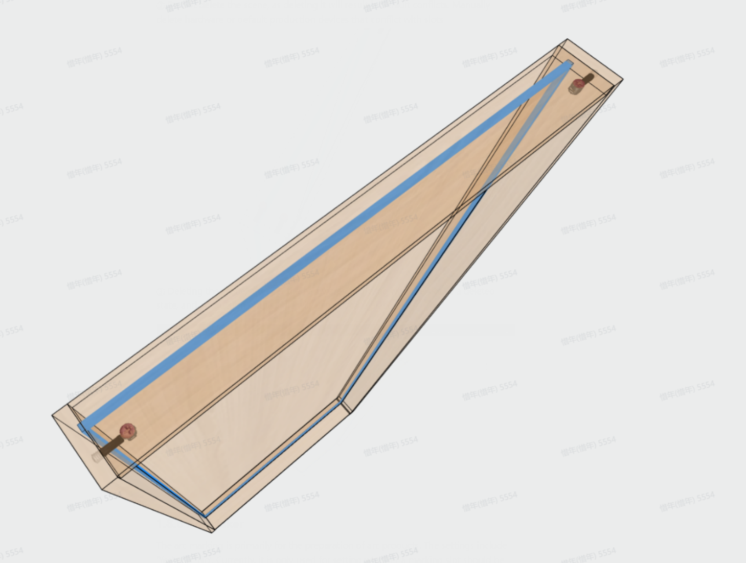
When arranging the manufacturing process, if the depth of a cabinet is too small, such as 80, and it still requires normal slotting, a situation may arise where a three-in-one fitting and the slot cannot avoid each other. In this case, the ability to delete fittings that conflict with slots can be used. The specific operation is as follows:
① In the settings, choose whether to delete the fittings in this scenario where conflicts occur with the slots.

② Do not delete the scene, as deleting it will result in default conflicts. Manually delete hardware or default production devices that conflict with slots
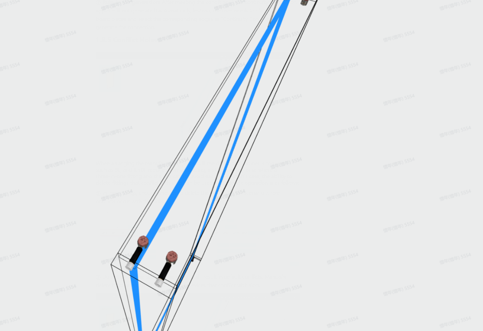
③ Deleting the scene, after set the hardware conflicting with the slot to a deleted state, and production of this hole will also not take place.
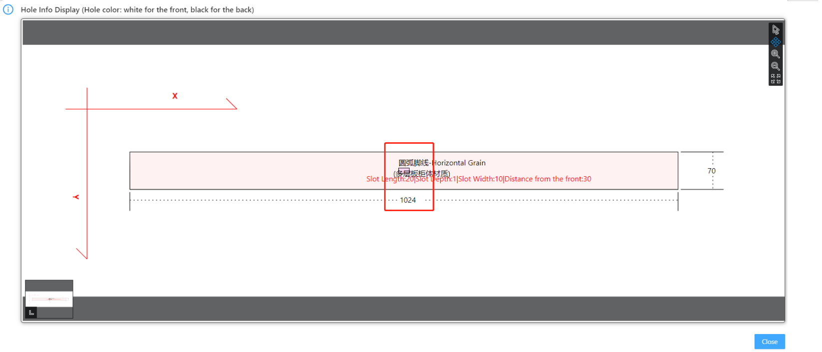
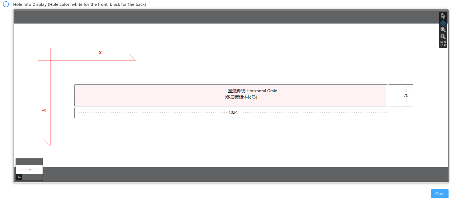
1.8.6 Arc Maker
The arc marking is primarily for the preparation of arc products. The settings include 'Yes' and 'No'. Currently, it is only used for setting whether a marking slot should be output in the middle of the strip for arc products, specifically those with the code 0502. If set to 'Yes', it will be output; otherwise, it won't be output.

① Select 'Yes' scene
② Select 'No' scene
9、Threshold Setting
9.1 Intersection Interface Threshold

Intersection Interface Threshold, This mainly controls whether a hole is produced within a specific gap range between two vertical boards. This value can be set by the user. For example, if the value is set to 0.5, the gap between the above-mentioned panel A and board B will not have a hole if it is greater than 0.5. Only when it is less than or equal to 0.5 will a connecting hole be generated. This is generally used to solve the hole production in the movable layer board. However, when using this setting, self-evaluation is still necessary to assess whether it may cause other issues.
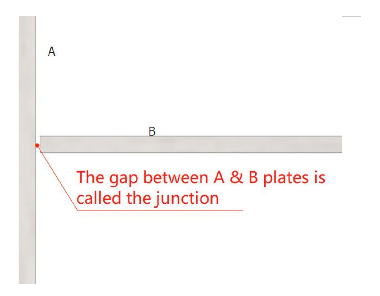
1.9.2 Intersect Threshold
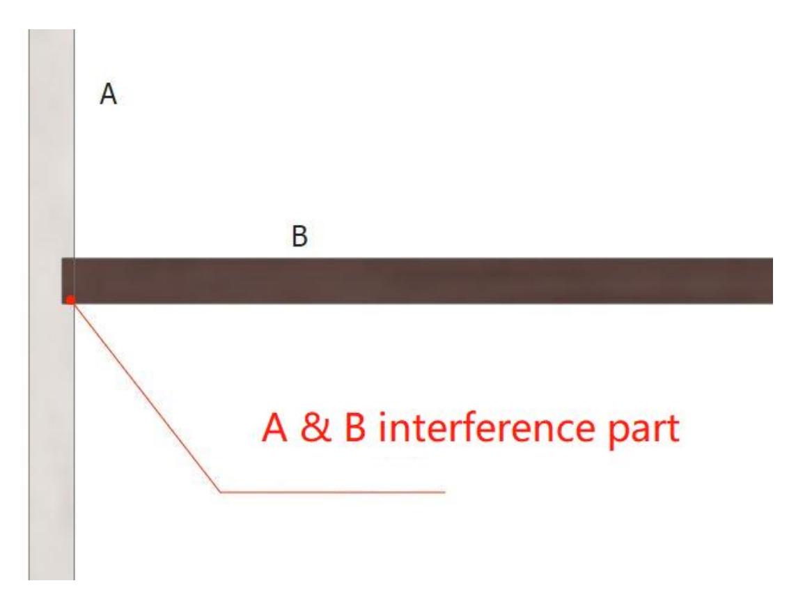
primarily controls whether a groove is created between two vertical and intersecting panels within a specific value range. This value can be set by the user. For example, if the value is set to 5, in the illustration, if the interference area between boards A and B is equal to or greater than 5, a groove will be created. If the interference area is less than 5, no groove will be created. When using this setting, it is also important to consider evaluating your own model library and manufacturing processes.
10、Door Panel Cabinet Hole Production
There are two scenarios:
① Flat Panel Doors: In the design process, there are cases where the door panel completely covers the neutral panel, top/bottom panels, etc. During the actual manufacturing process, only hardware holes such as hinge holes, handle holes, and straightener slots will typically be present on the door panel. There will be no holes generated on the opening side or the cabinet panels. Holes are only produced for fake doors or cover panels.
② Flat Drawer Fronts: The description for drawer fronts is the same as mentioned above. In the case of drawer fronts, when there are no recessed handles, the range below the drawer front may extend beyond the bottom panel or layer panel. However, during the actual manufacturing process, no holes will be generated on these panels. Only in the case of three-sided drawers, holes will be created on the drawer panels. In the following explanation, we will primarily address how to solve the hole production relationship between these two types of products and panels in the applet.
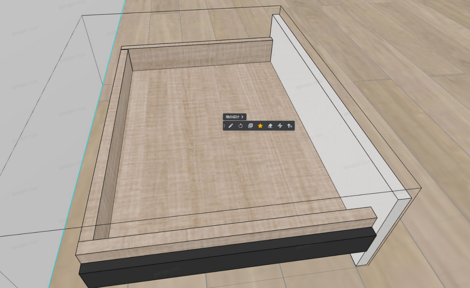
Solution:
When set to "default," both the door panels and drawer fronts will follow the previous hole production logic. If they meet the hole production conditions, holes will be generated. However, when set to "rule," the door panels and drawer fronts will not have holes produced in conjunction with the cabinet panels.

The above content includes (door panels, drawers), all of which are controlled by the "Default" and "Rules" buttons. Below are some examples of hole positions for drilling in both of these modes.
Tables can't be imported directly. Please insert an image of your table which can be found here.
Door panel type
Rules
Default: The previous judgment logic.
The bottom 0309 of the door panel has KMFX parameters, and the values are 0, 1, 2, and 3
Door panel bottom 0309 has not KMFX parameter
The bottom 0309 of the door panel has the KMFX parameter and the value is 4
The bottom layer 0309 has no parameter
The value of the bottom 0309 of the closing plate is 4
Frame door bottom 0309 No parameter
0303 Frame door, under 0309
Type 0302 plastic door
Other Setting
1、 Account Configuration

2.1.1 Processes Sharing
In applet, each account can independently set multiple sets of processes. When a factory wants all the requirements for separate processing to be unified, we can use the sub-account addition feature here. To do this, enter the name of the synchronized account in the sub-account name field and enter your own account password in the password field. Then click on "Add" to complete the process.

① After successful addition, the synchronized sub-account name will be displayed under the active account. You can also perform the sub-account unbinding operation from here.

② For the synchronized account, this interface will prompt whether to synchronize the options. Selecting "Yes" will produce according to the configuration shared by the active account. Selecting "No" will produce according to the default configuration of the account itself.
Note: When a specific applet shares a process with other accounts, the account under that separate order becomes the current mini program's admin account. Only this main account can share processes, while other sub-accounts, regardless of whether they have synchronized processes or not, cannot share processes with other accounts.

If you need to unbind the actively synchronized account, you will need to go to the adim account and unbind all the sub-accounts. This will release the main account and return it to an empty state. After that, you can select which account should be the main account again and continue with normal operations.
2.1.2 Password
① New Password
After applying for a applet functionality, when you enter the mini program, there is no default password in the account configuration. You need to enter new password in the "New Password" field and click on "Modify" to set your new account password successfully.

② Modify Password
If you want to change your password, you must know the original password. Then, enter the original password and the new password in their respective fields. Finally, click on "Modify" to complete the password change process.

③ Reset Password
customers are unable to reset their passwords by themselves. If they forget their password and need to retrieve it, they can contact the implementation engineers
2、 Basic Setting

2.2.1 Company Setting
① Company Name:
-
Company Name: Once this name is set, the text will be synchronized to the main interface of the mini-program and displayed at the top left corner where the logo is.
Company Name: Once this name is set, the text will be synchronized to the main interface of the mini-program and displayed at the top left corner where the logo is.

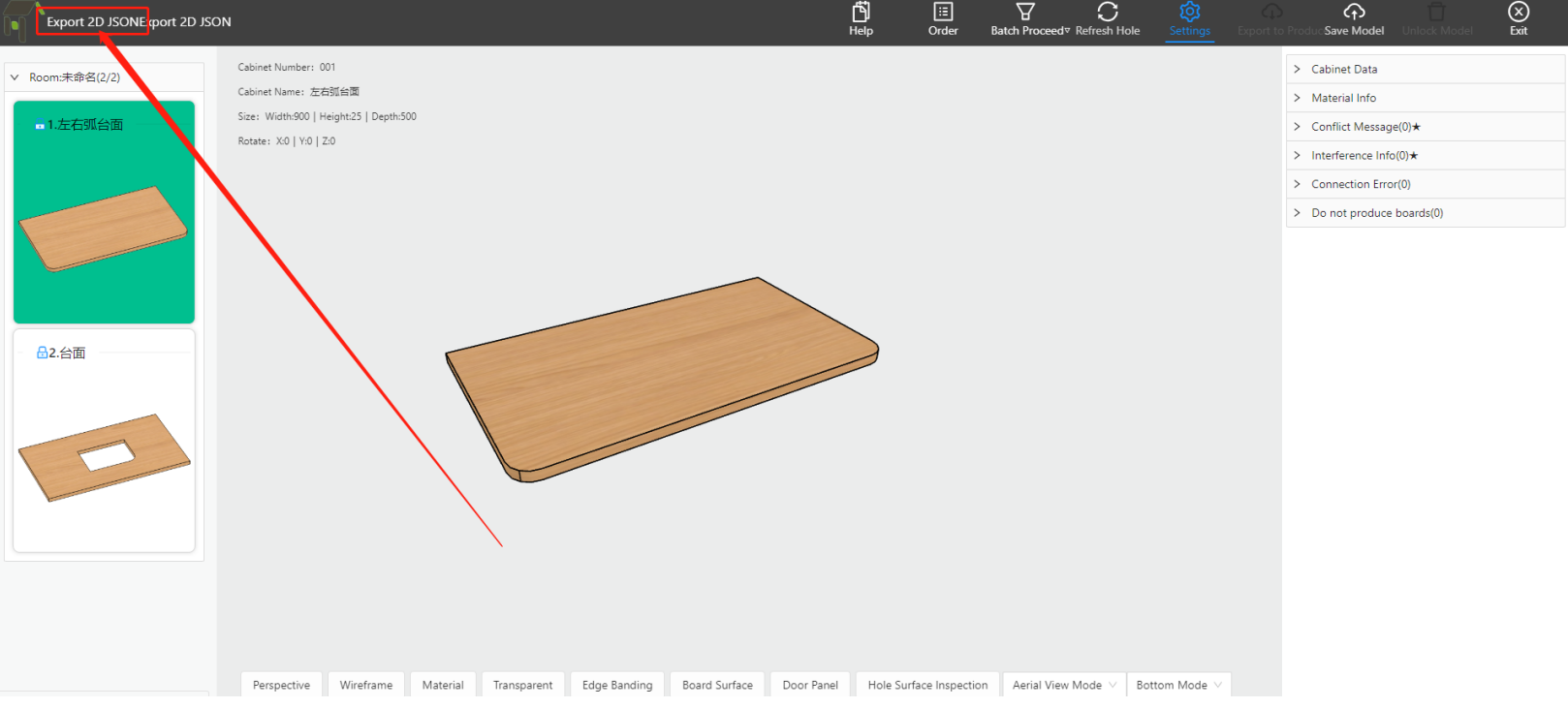
3、 Standby Capacity
3.1 Circular Arc Array Slot
3.2 Structural Hardware Fitting
Supports custom types, quantity configuration, and output.